Timepiece
a timepiece and timepiece technology, applied in the field of timepieces, can solve the problems of high probability of damage to the bezel, and high cost of polygonal springs
- Summary
- Abstract
- Description
- Claims
- Application Information
AI Technical Summary
Benefits of technology
Problems solved by technology
Method used
Image
Examples
first embodiment
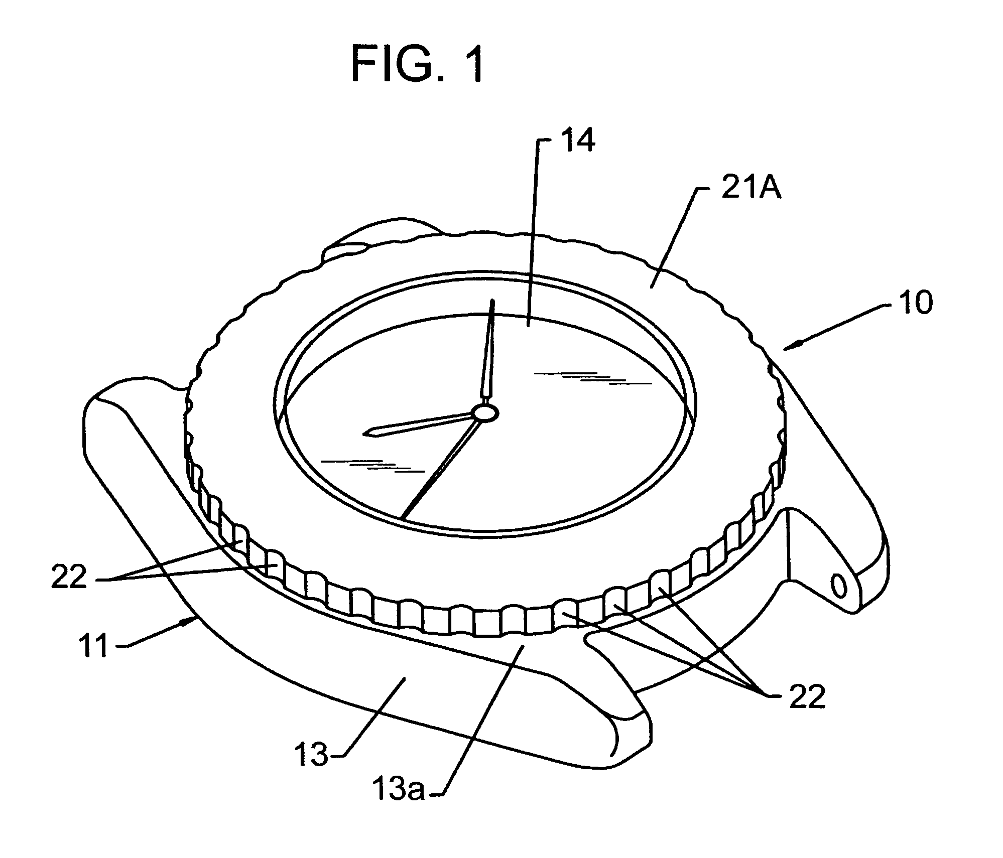
[0024]the present invention is hereinafter described in conjunction with FIGS. 1 through 3.
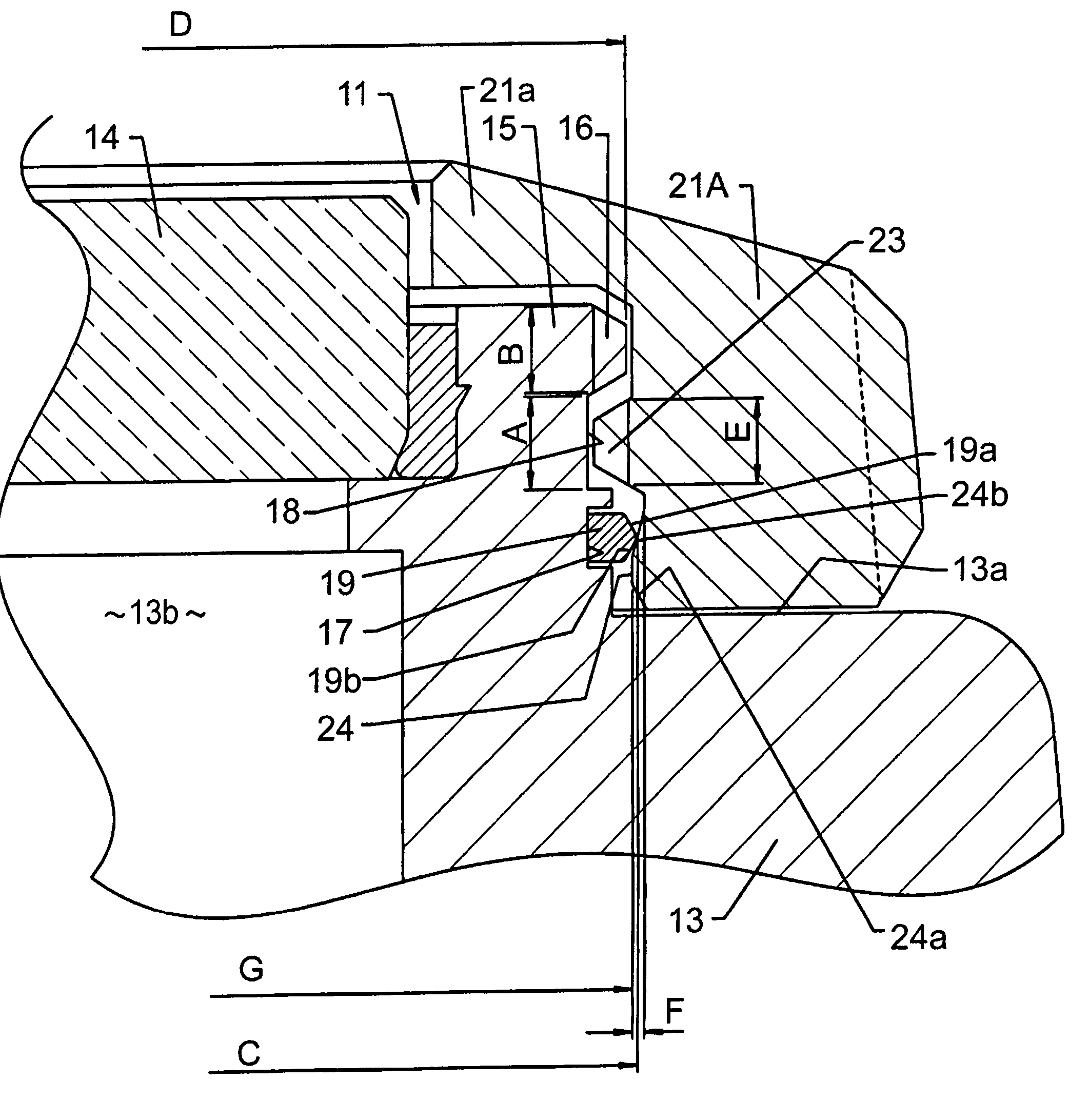
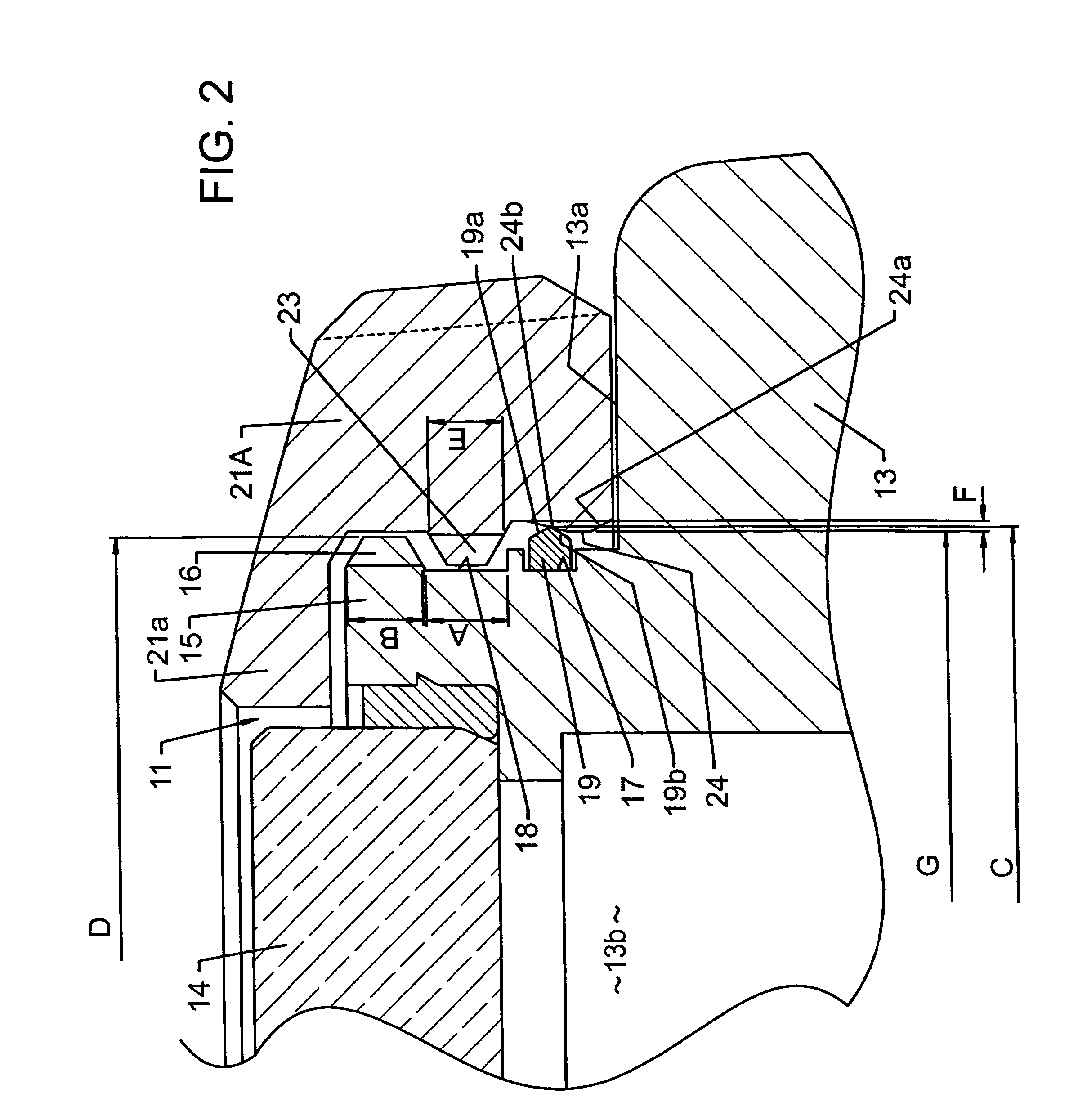
[0025]A reference numeral 11 in FIG. 1 denotes a watch which is attached to, for example, the wrist for use. A not-shown watch movement, a dial and other components are contained within a watch casing assembly 11 included in the watch 10. As illustrated in FIG. 2, the watch casing assembly 11 has an annular case band 13 made from metal or synthetic resin. A cover glass 14 is liquid-tightly attached to one face (front face) of the case band 13 in a thickness direction thereof, and a not-shown case back removably screwed into the other face (back face) of the case band 13 in the opposite thickness direction. The dial is visible through the cover glass 14.
[0026]An annular convex 15 formed integral with the case band 13 projects out to the front thereof. The cover glass 14 is attached to the inner periphery of the annular convex 15. A reference numeral 13a in FIG. 2 denotes a casing surface which ...
second embodiment
[0041]In the second embodiment, an annular groove 31 which opens to the casing surface 13a is formed on the case band 13. The groove 31 contains a flat spring 32 for positioning control. The flat spring 32 stops its rotation by inserting a plurality of stopper pieces 32b (only one piece shown) folded at the back face of an annular base 32a into engagement holes 33 continuously formed at a part of the groove 31. The surface of the flat spring 32 has a plurality of orthogonally cut and raised spring pieces 32c (only one piece shown) whose tips are folded as engagement ends. Engagement concaves 34 are formed on the lower surface of the bezel 21A at fixed intervals in the circumferential direction thereof.
[0042]During the rotational operation of the bezel 21A, the engagement ends of the spring pieces 32c engage with and disengage from the engagement concaves 34 with the spring pieces 32c elastically deformed. Thus, the rotation of the bezel 21A can be positioned at fixed angles. When it...
third embodiment
[0045]In the third embodiment, the engagement ring 19 is fitted to the annular groove 17 formed on the inner periphery of the bezel 21A instead of being attached to the annular convex 15 of the case band 13, and accordingly the annular engagement convex 24 is provided on the annular convex 15 of the case band 13 instead of being equipped on the inner periphery of the bezel 21A.
[0046]In this structure, a maximum diameter H of the engagement convex 24 and an inside diameter I of the engagement ring 19 are both larger than the outside diameter D of the male screw 16. Also, the maximum diameter H of the engagement convex 24 is larger than the inside diameter I of the engagement ring 19. Thus, in the condition in which the bezel 21A is fitted to the case band 13, the inner periphery of the engagement ring 19 passes through the outer peripheral projecting end of the engagement convex 24 downwardly, where the inner periphery of the engagement ring 19 is resiliently brought into tight conta...
PUM
 Abstract
Description
Claims
Application Information
 - R&D
- Intellectual Property
- Life Sciences
- Materials
- Tech Scout
- Unparalleled Data Quality
- Higher Quality Content
- 60% Fewer Hallucinations
Browse by: Latest US Patents, China's latest patents, Technical Efficacy Thesaurus, Application Domain, Technology Topic, Popular Technical Reports.
© 2025 PatSnap. All rights reserved.Legal|Privacy policy|Modern Slavery Act Transparency Statement|Sitemap|About US| Contact US: help@patsnap.com


