Apparatus for driving an accessory gearbox in a gas turbine engine

a technology for gas turbine engines and accessory gearboxes, which is applied in the direction of toothed gearings, belts/chains/gearings, and toothed gearings, etc., can solve the problems of limited power off the high-pressure drive shaft, and achieve the effect of increasing versatility and capability

Inactive Publication Date: 2006-06-06
UNITED TECH CORP
View PDF3 Cites 82 Cited by
  • Summary
  • Abstract
  • Description
  • Claims
  • Application Information

AI Technical Summary

Benefits of technology

[0006]One of the advantages of the present invention mechanical drive system for an accessory gearbox is that it provides increased versatility and capability over prior art mechanical drive systems that utilize a tower shaft engaged with the high pressure drive shaft. For example, in some applications it is possible to draw more power off of the low-pressure shaft than the high-pressure shaft without materially affecting the performance of the engine.

Problems solved by technology

The ability to tap power off of the high-pressure drive shaft is limited, however.

Method used


Image

  • Apparatus for driving an accessory gearbox in a gas turbine engine
  • Apparatus for driving an accessory gearbox in a gas turbine engine
  • Apparatus for driving an accessory gearbox in a gas turbine engine

Examples


Embodiment Construction

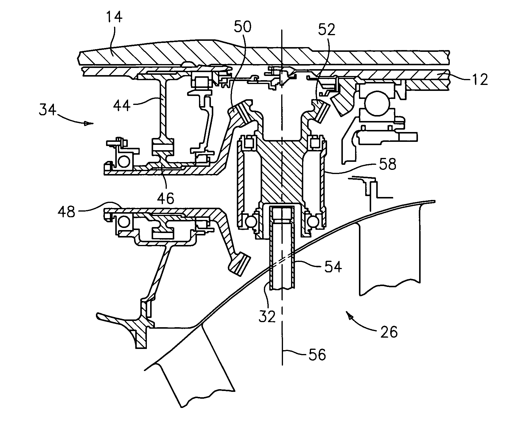
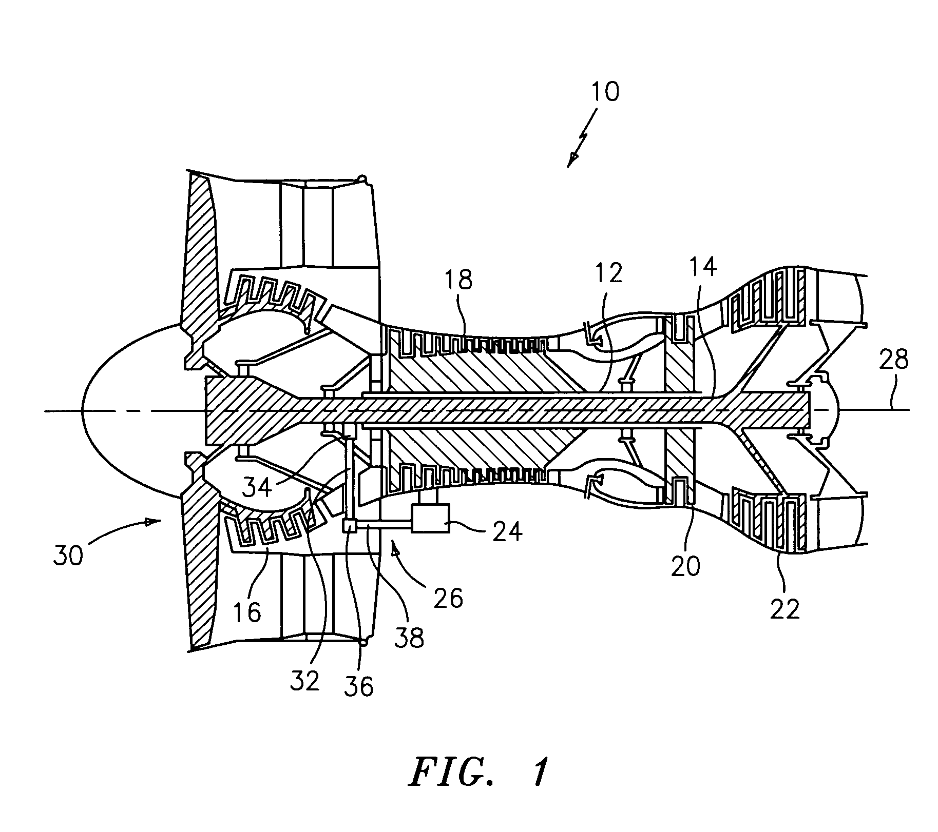
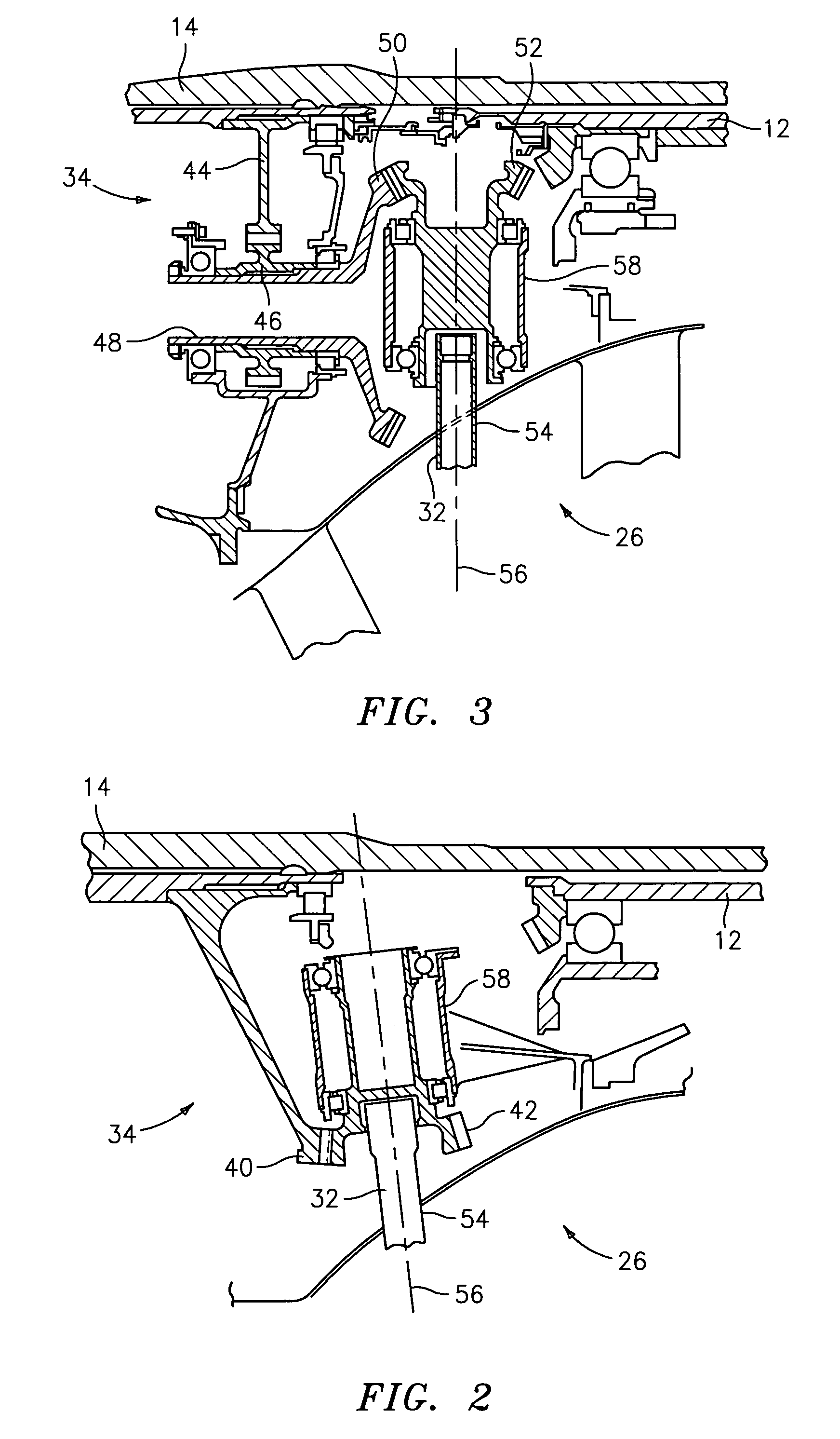
[0012]Referring to FIG. 1, a gas turbine engine 10 is diagrammatically shown. The engine 10 includes a high-pressure drive shaft 12, a low-pressure drive shaft 14, a low-pressure compressor 16, a high-pressure compressor 18, a high-pressure turbine 20, a low-pressure turbine 22, an accessory gearbox 24, and a mechanical drive system 26 for the accessory gearbox 24. The drive shafts 12, 14, compressor sections 16, 18, and turbine sections 20,22 are centered about an axially extending engine centerline 28.

[0013]The low-pressure compressor 16 is disposed axially forward of the high-pressure compressor 18, and the high pressure turbine 20 is positioned forward of the low-pressure turbine 22. The terms “forward” and “aft” are used to indicate position along the axially extending engine centerline 28. A first component “forward” of a second component is positioned closer to the inlet 30 of the engine 10. The second component is positioned “aft” of the first component. In most instances, g...


PUM


Abstract

A mechanical drive system for an accessory gearbox of a gas turbine engine is provided. The gas turbine engine includes a high-pressure drive shaft and a low-pressure drive shaft. The mechanical drive system includes a tower shaft and a lay shaft. The tower shaft is connected by a first gear arrangement to the low-pressure drive shaft of the gas turbine engine. The lay shaft is connected by a second gear arrangement to the first tower shaft, and connected to the accessory gearbox.

Description

BACKGROUND OF THE INVENTION[0001]1. Technical Field[0002]The present invention relates to gas turbine engines in general, and to apparatus for driving an accessory gearbox in particular.[0003]2. Background Information[0004]Aircraft powered by gas turbine engines very often include a mechanically driven accessory gearbox for driving accessory systems such as fuel pumps, scavenge pumps, electrical generators, hydraulic pumps, etc. The power requirements of the accessory gearbox continue to increase as the number of electrical systems within the aircraft increase. Historically, the accessory gearbox has been driven by a mechanical system connected to the drive shaft (i.e., the “high pressure drive shaft”) extending between the high-pressure turbine and the high-pressure compressor of the gas turbine engine. The ability to tap power off of the high-pressure drive shaft is limited, however. What is needed is an apparatus for mechanically driving an accessory gearbox that can accommodate ...

Claims


Application Information

Patent Timeline
Patent Type & Authority Patents(United States)
IPC IPC(8): F02C7/32F02C7/36F02B61/06F16H1/14
CPCF02C7/32F02C7/36Y10S74/05F05D2260/4031F05D2260/53
Inventor MILLER, GUY WALLACE
Owner UNITED TECH CORP
Why Eureka
Try Eureka