Marker layout method, mixed reality apparatus, and mixed reality space image generation method

a technology of mixed reality and marker layout, applied in the field of marker layout method, mixed reality apparatus, and mixed reality space image generation method, can solve the problems of difficult to satisfy, difficult to observe at equal intervals from another player, and difficulty in detecting markers in units of players

Inactive Publication Date: 2006-08-01
CANON KK
View PDF30 Cites 91 Cited by
  • Summary
  • Abstract
  • Description
  • Claims
  • Application Information

AI Technical Summary

Benefits of technology

[0015]It is an object of the present invention to provide a marker layout method in a mixed reality space, which can solve the aforementioned problems, and can reliably detect markers in units of players even when a plurality of players share a common mixed reality space.
[0016]It is another object of the present invention to provide a marker layout method in a mixed reality space, which can present the number of markers from simply increasing even when the number of players increases.
[0018]It is still another object of the present invention to provide a mixed reality apparatus and a mixed reality space image generation method, which can solve the aforementioned problems, and allow a player to experience mixed reality without being bothered by the presence of markers.

Problems solved by technology

However, in an application which allows a plurality of players to share a common MR space, markers which are laid out at equal intervals at positions that can be observed from a given player cannot often be observed at equal intervals from another player.
However, marker layout using different colors becomes harder with increasing number of players who share a single MR space.
However, when the number of colors used increases, it becomes difficult to satisfy such conditions, and extraction errors and identification errors among markers can occur.
In this manner, when the number of players increases and similar colors are used as markers, even though a player observes a red marker, the marker may be detected as color of region B (i.e., of orange marker), thus causing detection errors.
When a plurality of markers having different colors in units of players are laid out, a very large number of markers appear in the real space, and may complicate the vision of the player, thus impairing reality upon experiencing an MR space.

Method used


Image

  • Marker layout method, mixed reality apparatus, and mixed reality space image generation method
  • Marker layout method, mixed reality apparatus, and mixed reality space image generation method
  • Marker layout method, mixed reality apparatus, and mixed reality space image generation method

Examples


Embodiment Construction

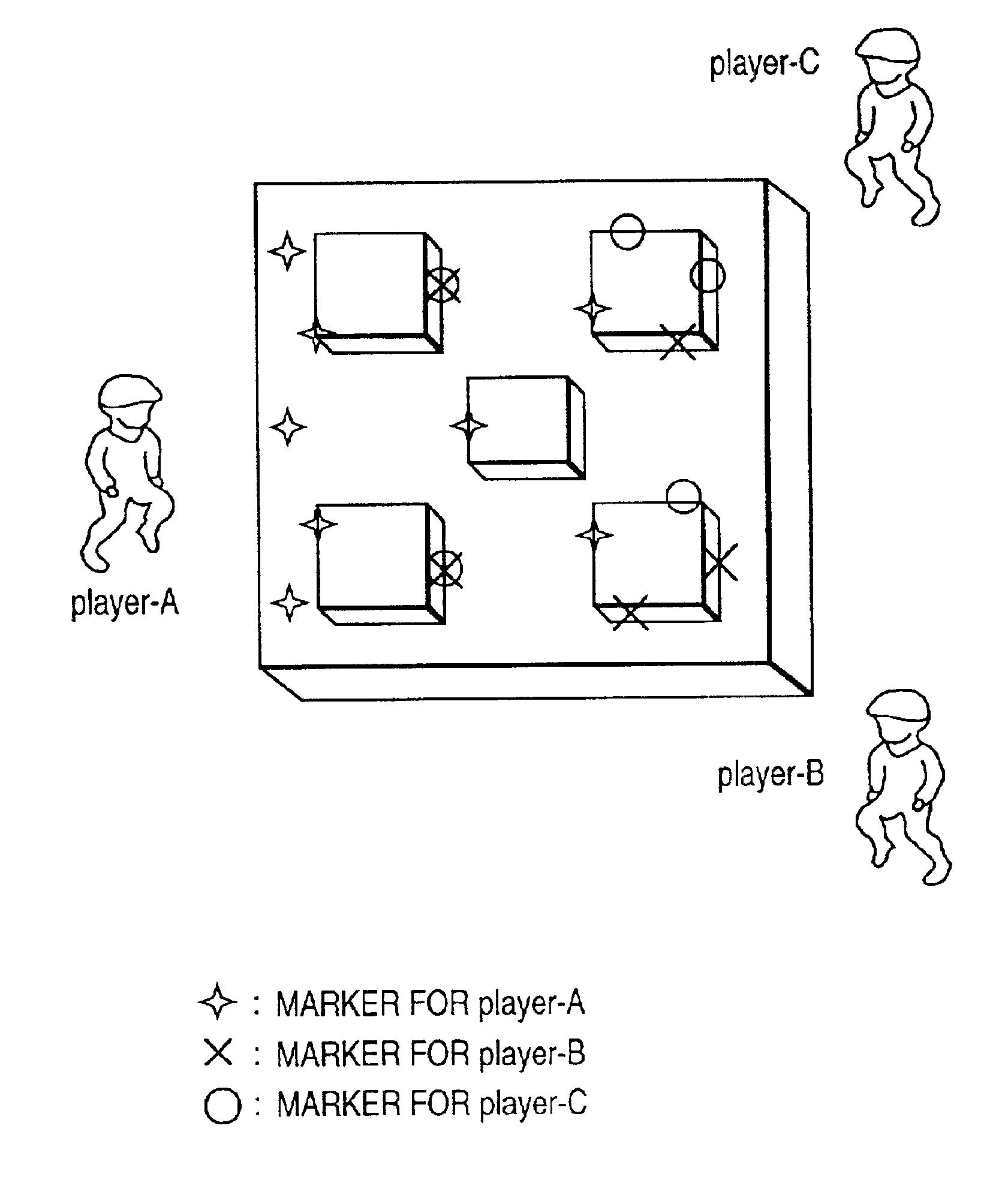
[0038]A preferred embodiment of a marker layout method according to the present invention will be described hereinafter with reference to the accompanying drawings. In this embodiment, the present invention is applied to an MR game played by three players while sharing a single virtual space, but a marker layout method in an MR space according to the present invention can be applied to any other arbitrary applications.

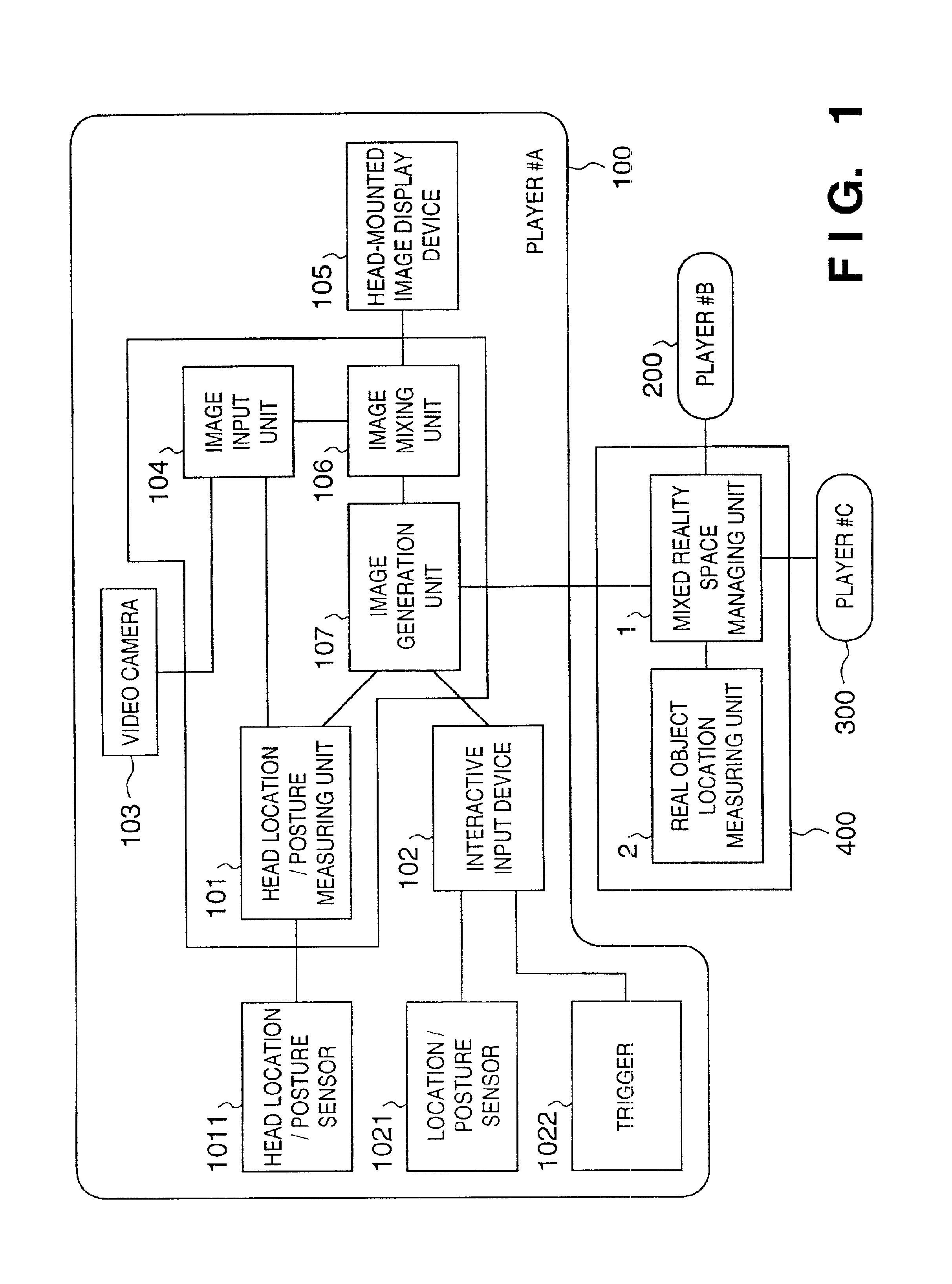
[0039]FIG. 1 shows the arrangement of an MR apparatus for implementing an MR game to which a marker layout method of the present invention is applied. FIG. 1 shows the arrangement for three players. The MR apparatus comprises player processors 100 to 300 provided in units of players, and a controller 400 connected to the player processors. The number of player processors connected to the controller 400 increases with increasing number of players.

[0040]The player processors 100 to 300 have an identical arrangement. That is, each player processor comprises I / O blocks (10...


PUM


Abstract

There is disclosed a marker layout method in a mixed reality space, which can reliably detect markers in units of players, even when a plurality of players share a common mixed reality space. According to this invention, markers to be used by only a given player are laid out at positions that cannot be seen from other players. Real objects used in an application that uses a mixed reality space may be used.

Description

FILED OF THE INVENTION[0001]The present invention relates to a method of laying out a marker used as a position index upon presenting a mixed reality space and, more particularly, to a marker layout method which allows easy detection of a marker even when a plurality of players share a mixed reality space, and a mixed reality apparatus using the same.BACKGROUND OF THE INVENTION[0002]In recent years, Mixed Reality (MR) that aims at seamlessly coupling a real space and virtual space has been extensively studied. MR has received a lot of attention as a technique which aims at realizing coexistence of a virtual reality (VR) world that can be expressed in only a situation isolated from a real space, and the real space, and augments VR.[0003]A typical apparatus for implementing MR is a head-mounted display (HMD). More specifically, MR is implemented by mixing and displaying real and virtual spaces on the HMD. MR schemes using the HMD include an optical see-through scheme for superposing a...

Claims


Application Information

Patent Timeline
Patent Type & Authority Patents(United States)
IPC IPC(8): G09G5/00G06K9/00A63F3/00A63F13/10G06F3/01G06T7/00
CPCA63F13/10G06T19/006G06F3/012G06F3/017G06T7/0042A63F2300/1012A63F2300/1087A63F2300/303A63F2300/306A63F2300/69A63F2300/8082A63F2300/66G06T7/73A63F13/45A63F13/5372A63F13/213A63F13/65
Inventor SATO, KIYOHIDEOHSHIMA, TOSHIKAZU
Owner CANON KK
Why Eureka
Try Eureka