Thermally efficient LED bulb

a technology of led bulbs and led bulbs, applied in the direction of packaging, lighting support devices, coupling device connections, etc., can solve the problems of excess heat having a deleterious effect on the lamp employing the leds, the device does not meet federal regulations, and the amount of heat generated is increased

Active Publication Date: 2006-08-08
OSRAM GMBH
View PDF12 Cites 216 Cited by
  • Summary
  • Abstract
  • Description
  • Claims
  • Application Information

AI Technical Summary

Benefits of technology

[0007]This construction allows for multiple solid-state devices to be employed to insure adequate light output and the metal core provides adequate heat removal.

Problems solved by technology

For the most part, these devices do not meet Federal regulations.
Further, it has been found necessary to greatly multiply the number of individual LED units to increase the light output to meet Federal regulations; however, this increase in number has also increased the amount of heat generated and this excess heat has a deleterious effect on the lamp employing the LEDs.

Method used


Image

  • Thermally efficient LED bulb
  • Thermally efficient LED bulb
  • Thermally efficient LED bulb

Examples


Embodiment Construction

[0013]For a better understanding of the present invention, together with other and further objects, advantages and capabilities thereof, reference is made to the following disclosure and appended claims taken in conjunction with the above-described drawings.

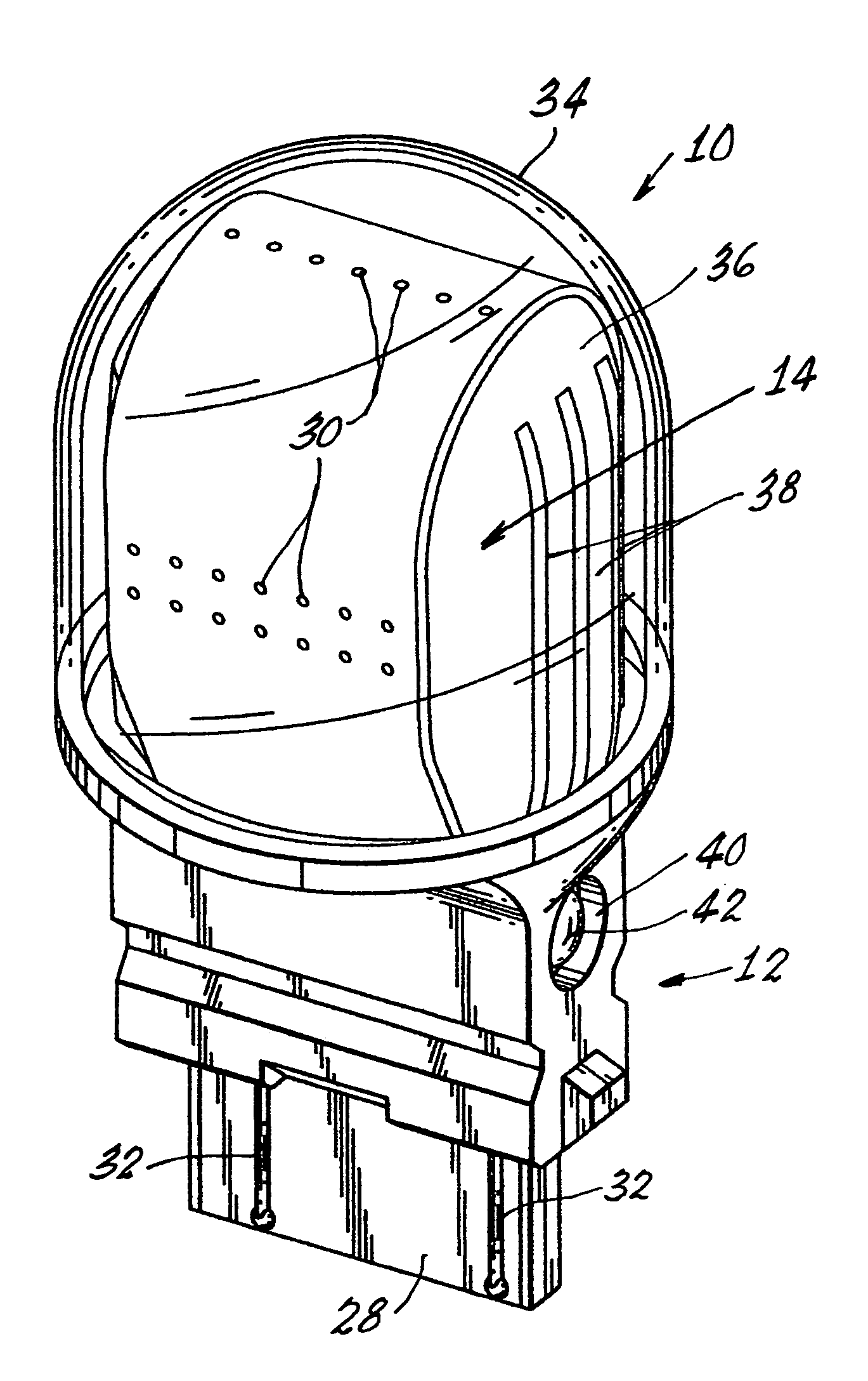
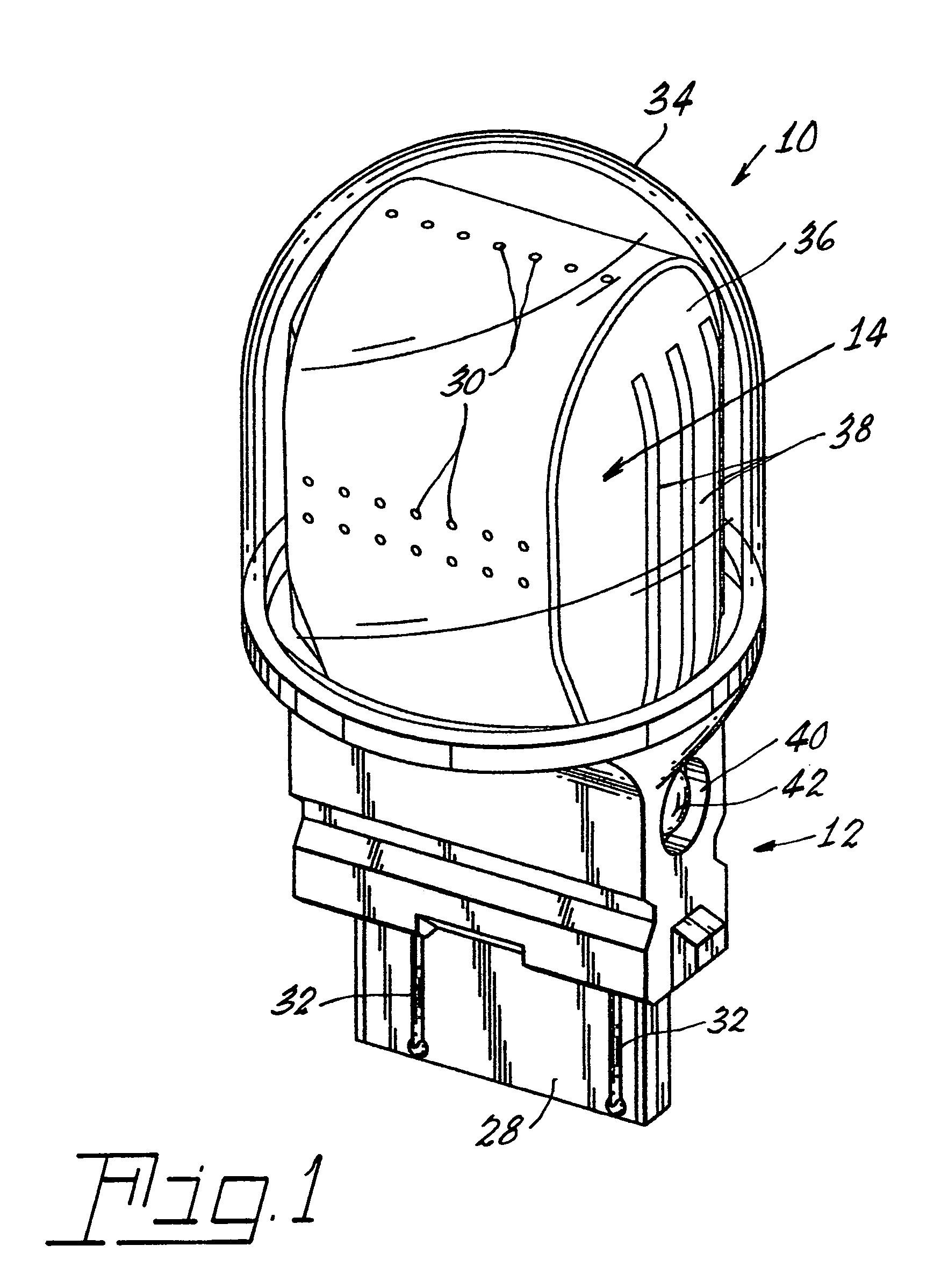
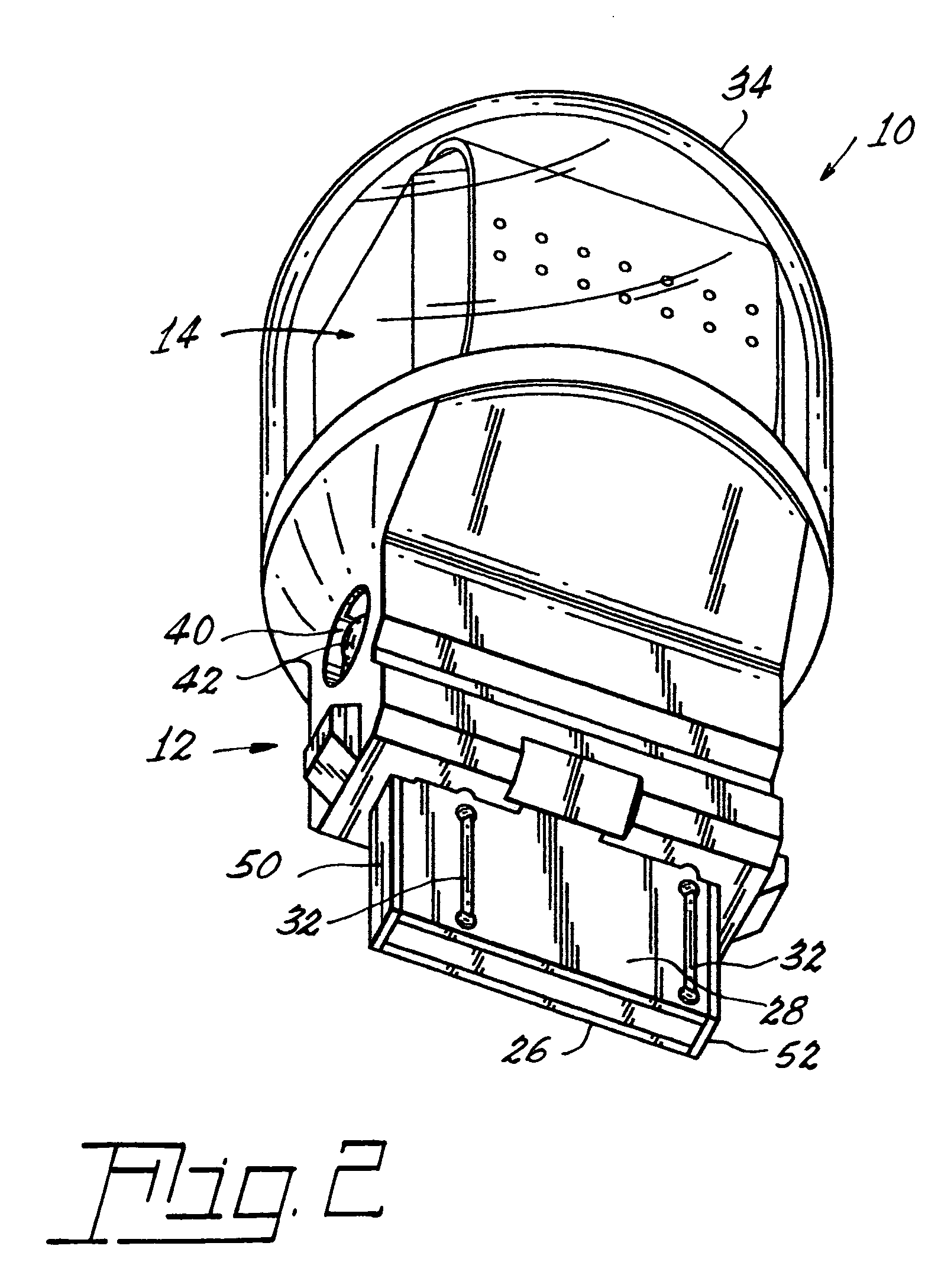
[0014]Referring now to the drawings with grater particularity, there is shown in FIG. 1 a solid-state light source 10 compatible with existing sockets normally reserved for filamented lamps. The light source 10 comprises a hollow base 12 formed to mechanically and electrically adapt to a socket. The base 12 is preferably formed of plastic; however, in the event that additional heat dissipation is required, metal, with suitable insulating features, can be employed. A sub-assembly 14 that is adapted to cooperate with and fit into the hollow base 12 comprises a metal core 16 having a bulbous body 18 and a narrow foot 20 depending therefrom. The metal core 16 is preferably made from solid copper; however, other metals can be used, fo...


PUM


Abstract

A solid-state light source 10 compatible with existing sockets normally reserved for filamented lamps may be formed with a hollow base 12 formed to mechanically and electrically adapt to a socket. A sub-assembly 14 adapted to cooperate with and fit into the hollow base 12 comprises a metal core 16 having a bulbous body 18 and a narrow, depending foot 20. A circuit board 22 substantially surrounds the metal core 16 on two sides. The board 22 is preferably formed from a flexible printed circuit board material capable of sustaining a bend radius of at least 0.25 inches (6 mm). Solid-state light sources 30, for example, light emitting diodes (LEDs) are mechanically and electrically connected to one side of the circuit board by suitable electrically conductive traces. A glass dome 34 covers the sub-assembly 14 after it is inserted into the hollow base 12 and is sealed thereto.

Description

TECHNICAL FIELD[0001]This invention relates to light sources and more particularly to solid-state light sources. Still more particularly it relates to solid-state light sources that can be employed with a reflector to mimic the light distribution of an incandescent light. Still more particularly, it relates to solid-state light sources useable as direct replacements for automotive signal lighting, such as taillights and to such light sources having a viable heat transfer mechanism.BACKGROUND ART[0002]Solid-state lighting, for example, light emitting diodes (hereinafter, LED) are renowned for their long life and their ability to resist shock. They have been used for some time as the high-mount stop light in automobiles, where no particular amplification or reflection of the light is needed. Attempts have been made in the past to adapt LEDs for other purposes such as taillight units; however, these attempts have applied LEDs typically encased in plastic beads to flat surfaces, which w...

Claims


Application Information

Patent Timeline
Patent Type & Authority Patents(United States)
IPC IPC(8): F21S8/10F21V21/00F21V7/04F21V19/00F21K99/00F21S2/00F21V29/00
CPCF21V3/00F21V29/767F21K9/135F21V29/763F21W2101/14F21Y2101/02F21Y2111/005F21V29/58F21K9/232F21Y2107/30F21Y2115/10F21S43/14F21S43/195F21S45/47A45D34/042A45D40/20A45D2034/002A45D2040/201B65D83/0033F21W2103/00
Inventor SIDWELL, STEVEN C.COUSHAINE, CHARLES M.LYMAN, PAUL
Owner OSRAM GMBH
Why Eureka
Try Eureka