Ratchet interlocking housing

a technology of interlocking housings and ratchets, which is applied in the direction of threaded fasteners, screws, bolts, etc., can solve the problems of repetitive motion injuries, unnecessarily consuming time, and taking numerous rotations of nuts, and achieve the effect of restricting the movement of sound

Active Publication Date: 2006-08-15
FLOYD BELL
View PDF27 Cites 27 Cited by
  • Summary
  • Abstract
  • Description
  • Claims
  • Application Information

AI Technical Summary

Problems solved by technology

One difficulty with a conventional nut and bolt is that it often takes numerous rotations of the nut relative to the bolt to tightly interpose the structure between the head and nut.
Furthermore, if carried out by hand, these numerous rotations may consume time unnecessarily or cause repetitive-motion injuries, such as carpal-tunnel syndrome.
Such devices have the disadvantage that they still require some rotation.
An additional disadvantage is that the pitch and coarseness of the threads must be such that the fastener can be tightened on opposite sides of the structures on which it is attached within the partial rotation permitted before the threads disengage.
Otherwise, the fasteners will disengage without being sufficiently tightened.
A disadvantage of such a device is that the tightening force on the nut also tends to displace the threaded structures radially, thereby permitting the nut to back off and loosen the fastener.
Thus, any over-tightening might cause the nut to come loose over time, especially in an environment in which there is vibration.

Method used


Image

  • Ratchet interlocking housing
  • Ratchet interlocking housing
  • Ratchet interlocking housing

Examples


Embodiment Construction

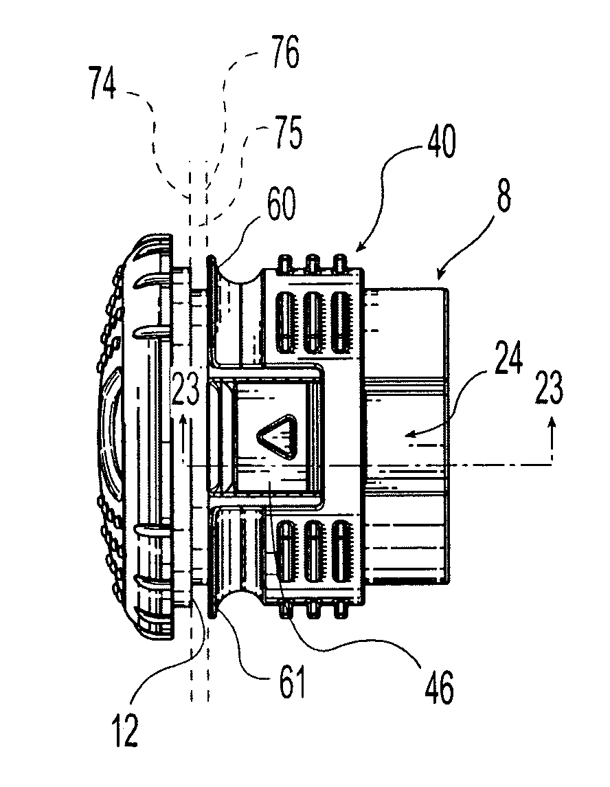
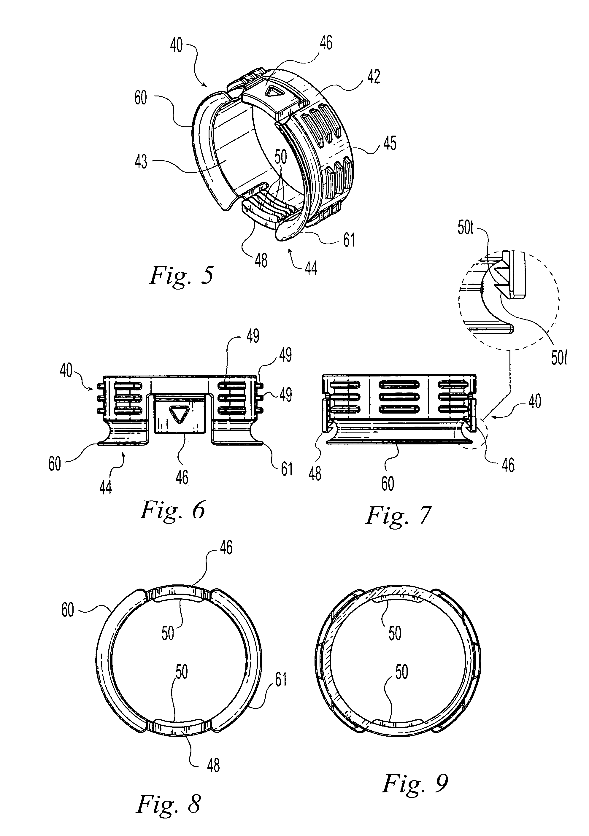
[0053]The preferred embodiment of the present invention has two main components: a shank member 8 and a nut member 40. In a preferred configuration, the nut member 40 is mounted to the shank member 8 after the shank member 8 is inserted through an aperture in a panel or another structure. The shank member 8 is installed through the panel aperture with the head 10 of the shank member 8 at the front of the panel and the nut member 40 at the rear. Of course, this could be reversed, for example, for switches mounted in the shank member 8.

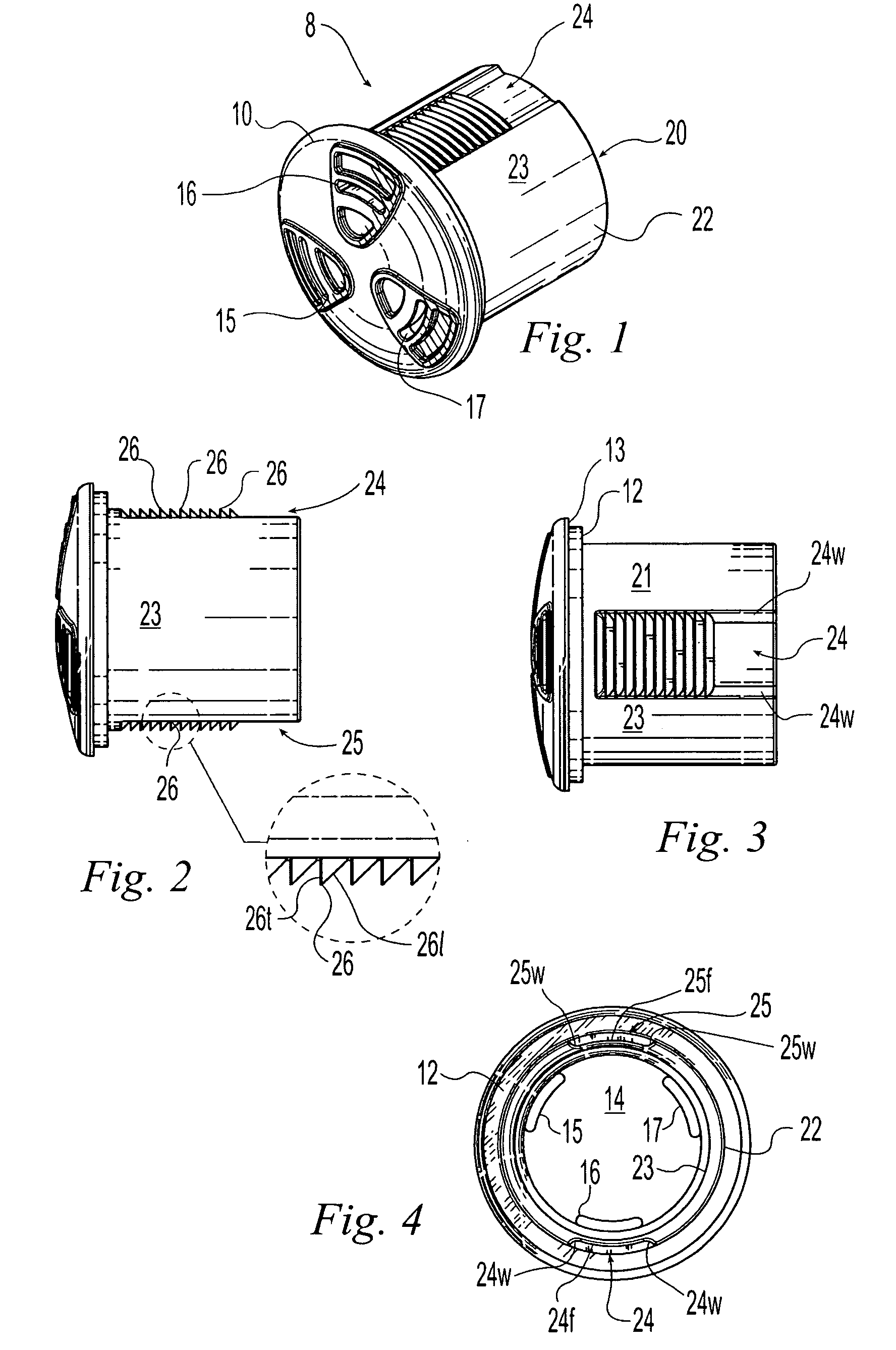
[0054]The shank member is shown in FIGS. 1 through 4 having the head 10 and a sidewall 20. The sidewall 20 is preferably a circular cylindrical body having a radially outwardly facing surface 22 and an opposing radially inwardly facing surface 23. The outwardly facing surface 22 has longitudinal channels 24 and 25 formed on substantially opposite sides of the sidewall 20, and longitudinal smooth regions 21 and 23 between the channels 24 and 25 that sepa...


PUM


Abstract

A fastener, such as a housing, for mounting to a structure, such as a panel, that has an aperture formed therethrough. The fastener includes a shank member and an annular nut member that is configured to align coaxially with the shank member. The shank member is inserted through aperture in the structure and the nut member is placed on the shank member. Teeth on the radially outwardly facing surface of the shank member engage a pawl, such as one or more teeth, on the radially inwardly facing surface of the nut member to lock the nut member to the shank member. Removal of the nut member is effected by rotating the nut member to disengage the pawl from the teeth, thereby permitting longitudinal displacement of the nut member off of the shank member.

Description

(b) CROSS-REFERENCES TO RELATED APPLICATIONS[0001]This application is a continuation-in-part of U.S. application Ser. No. 29 / 186,958 filed Jul. 24, 2003 entitled PANEL MOUNTED HOUSING.(c) STATEMENT REGARDING FEDERALLY-SPONSORED RESEARCH AND DEVELOPMENT[0002](Not Applicable)(d) REFERENCE TO AN APPENDIX[0003](Not Applicable)(e) BACKGROUND OF THE INVENTION[0004]1. Field of the Invention[0005]This invention relates generally to fasteners for mounting through an aperture in a structure, and more preferably to a fastener for mounting through an aperture in a panel where the fastener is configured to contain an object, such as a sound-emitting transducer, in the manner of a housing.[0006]2. Description of the Related Art[0007]There are many fasteners that are capable of fastening two or more structures together. The conventional wood or metal screw has helical threads around a shaft, and the threads seat against the inwardly facing wall of an aperture formed in the structures. As the scre...

Claims


Application Information

Patent Timeline
Patent Type & Authority Patents(United States)
IPC IPC(8): F16B21/02F16B21/06F16B37/00
CPCF16B37/00F16B21/065
Inventor SHAIN, THOMAS A.
Owner FLOYD BELL
Why Eureka
Try Eureka