Doorknob and lock light assembly

Inactive Publication Date: 2006-09-19
LUCAS DANIEL D
View PDF3 Cites 18 Cited by
  • Summary
  • Abstract
  • Description
  • Claims
  • Application Information

AI Technical Summary

Benefits of technology

[0011]Still another object of the present invention is to provide a new doorknob and lock light assembly for providing a useful light when for a user attempting to place a key in the lock.
[0012]Still yet another object of the present invention is to provide a new doorknob and lock light assembly that is easy and convenient to use.
[0013]Even still another object of the present invention is to provide a new doorknob and lock light assembly that allows a user to quickly get into one's residence for safety purposes without having to fumble around trying to unlock the door.

Problems solved by technology

While these devices fulfill their respective, particular objectives and requirements, the aforementioned patents do not disclose a new doorknob and lock light assembly.

Method used


Image

  • Doorknob and lock light assembly
  • Doorknob and lock light assembly
  • Doorknob and lock light assembly

Examples


Embodiment Construction

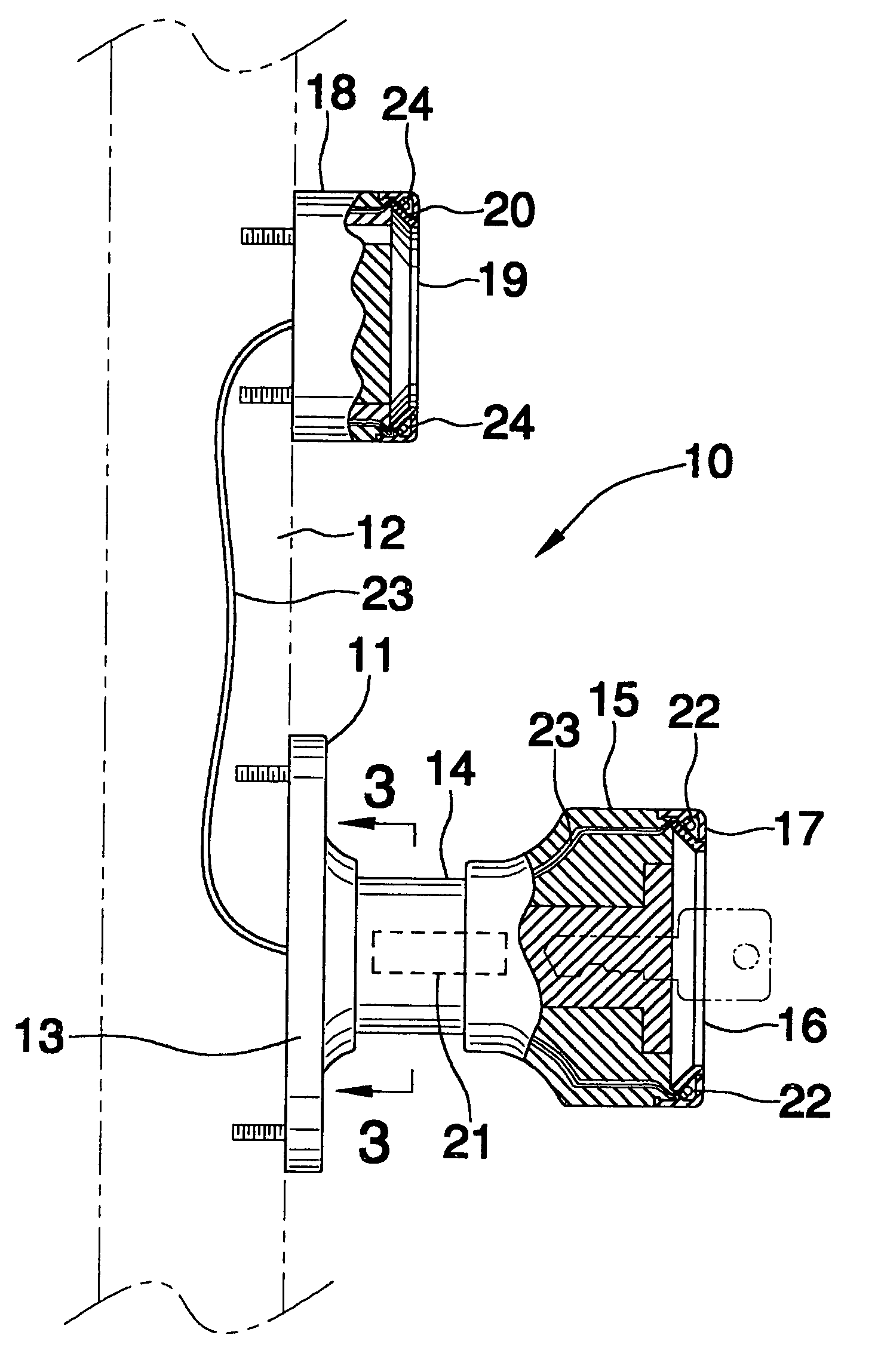
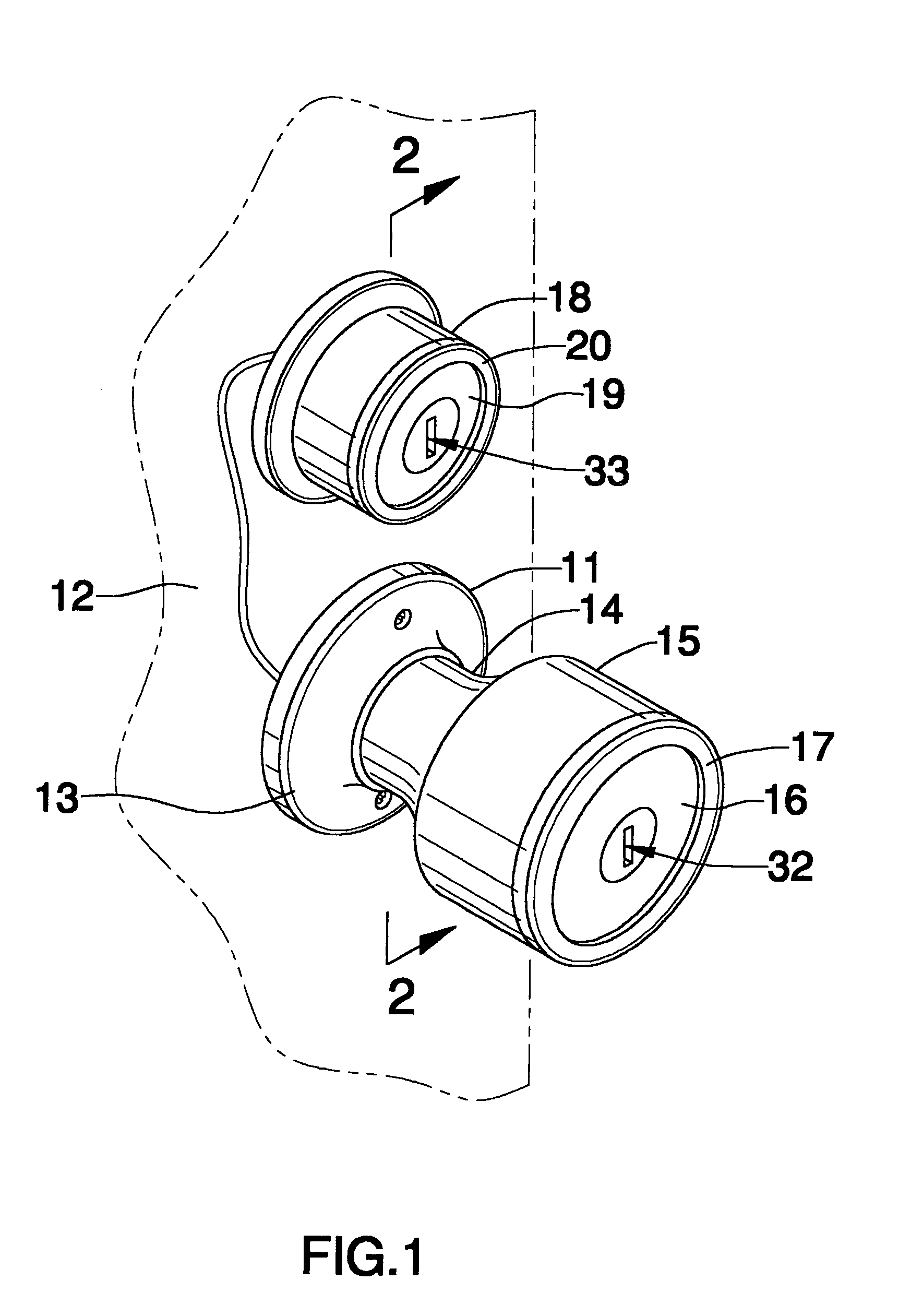
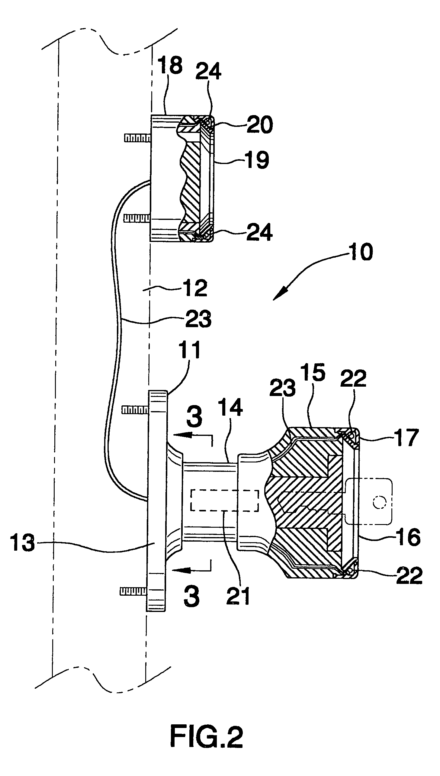
[0020]With reference now to the drawings, and in particular to FIGS. 1 through 4 thereof, a new doorknob and lock light assembly embodying the principles and concepts of the present invention and generally designated by the reference numeral 10 will be described.

[0021]As best illustrated in FIGS. 1 through 4, the doorknob and lock light assembly 10 generally comprises a door lock assembly including a handle 11 being adapted to be securely attached to a door 12. The handle 11 includes a face plate 13 being conventionally fastened to the door 12, and also includes a tubular shaft 14 being rotatably disposed through the face plate 13, and further includes a doorknob 15 having a front wall 16 and a keyhole 32 being conventionally disposed through the front wall 16. The doorknob 15 includes an annular transparent window 17 being conventionally disposed in the front wall 16 thereof. The door lock assembly further includes a lock housing 18 being securely and conventionally fastened to the...


PUM


Abstract

A doorknob and lock light assembly for providing a useful light when for a user attempting to place a key in the lock. The doorknob and lock light assembly includes a door lock assembly including a handle being adapted to be securely attached to a door; and also includes a light-emitting assembly being attached to the door lock assembly and including a battery being disposed in the handle and also including light-emitting members being attached to the handle and being connected with wires to the battery; and further includes a sensor / switch assembly being attached to the door lock assembly and being connected to the battery.

Description

BACKGROUND OF THE INVENTION[0001]1. Field of the Invention[0002]The present invention relates to doorknob and lock lighting arrangements and more particularly pertains to a new doorknob and lock light assembly for providing a useful light when for a user attempting to place a key in the lock.[0003]2. Description of the Prior Art[0004]The use of doorknob and lock lighting arrangements is known in the prior art. More specifically, doorknob and lock lighting arrangements heretofore devised and utilized are known to consist basically of familiar, expected and obvious structural configurations, notwithstanding the myriad of designs encompassed by the crowded prior art which have been developed for the fulfillment of countless objectives and requirements.[0005]Known prior art includes U.S. Pat. No. 5,398,175; U.S. Pat. No. 5,712,615; U.S. Pat. No. 6,278,366; U.S. Pat. No. 4,981,314; U.S. Pat. No. 5,008,551; and U.S. Patent No. Des. 338,735.[0006]While these devices fulfill their respectiv...

Claims


Application Information

Patent Timeline
IPC IPC(8): E05B17/10
CPCE05B1/0007E05B17/10Y10S362/802E05B17/22Y10T70/8027
Inventor LUCAS, DANIEL D.
Owner LUCAS DANIEL D
Why Eureka
Try Eureka