Filter for a propellant gas evacuation system

Active Publication Date: 2016-11-10
JUSTRITE MFG
View PDF1 Cites 7 Cited by
  • Summary
  • Abstract
  • Description
  • Claims
  • Application Information

AI Technical Summary

Benefits of technology

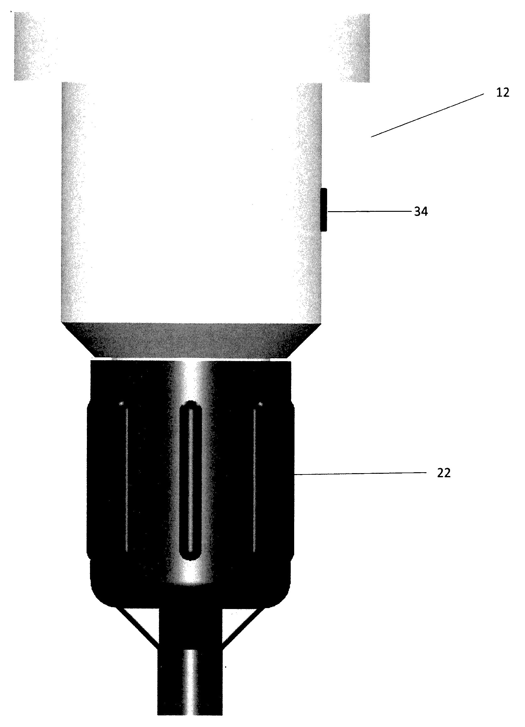
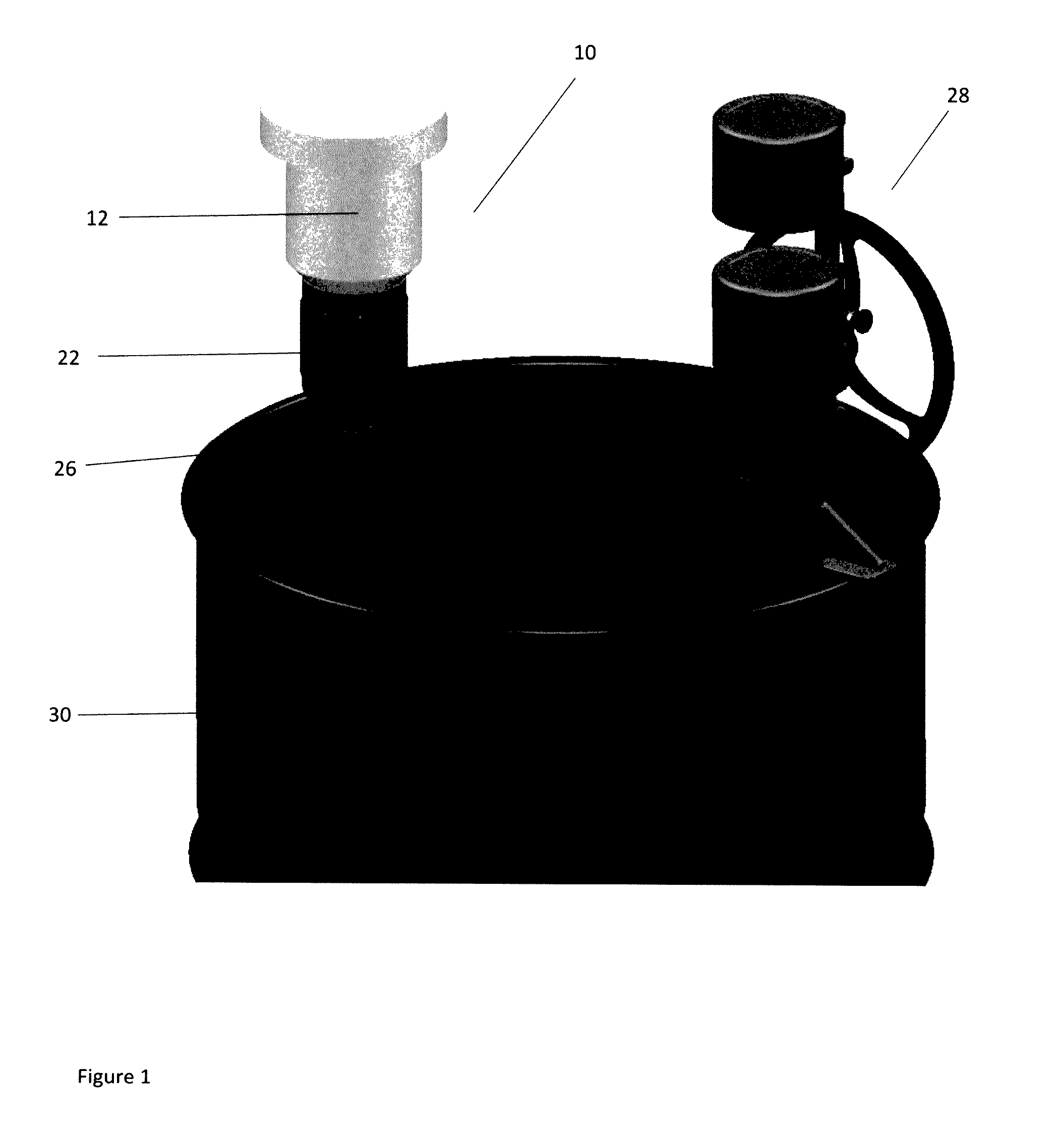
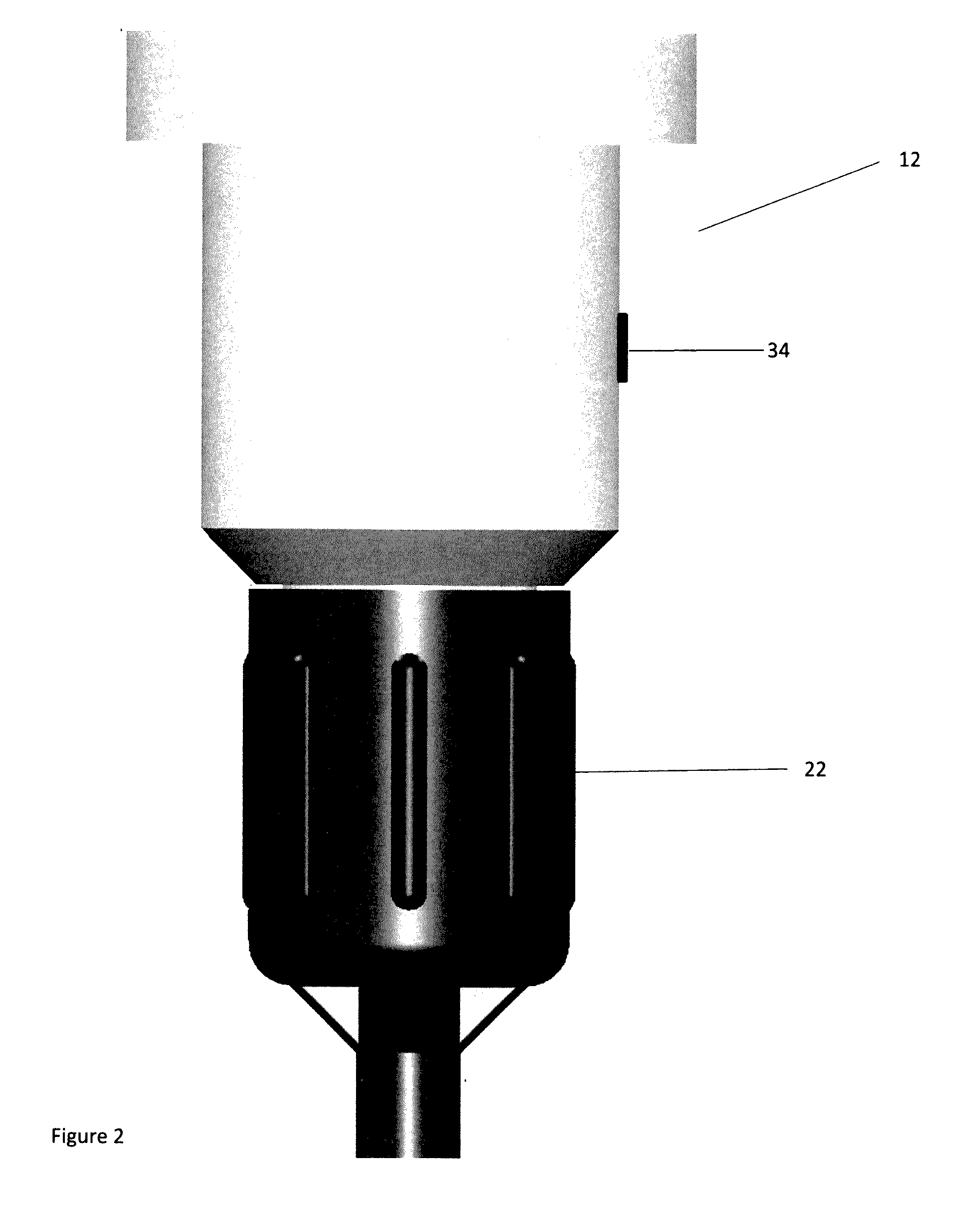
The present invention is about a device that filters exhaust fumes from a storage container. It has two filter chambers, one containing activated carbon to filter residue from the exhaust fumes, and one containing a coalescing filter to filter residue from the exhaust fumes. A visual indicator indicates when the filter is saturated with residue, and a flashback inhibitor prevents flashback of the exhaust fumes. The device is made from aircraft grade aluminum or polyethelene, and its upper and lower chambers are connected by an airtight, threaded connection. The invention can effectively protect the environment from harmful exhaust fumes.

Problems solved by technology

It has long been recognized that improper disposal of such containers constitutes a safety hazard in that excessive external heat and / or pressure can cause them to explode if they have not been relieved of internal pressure.
Similarly, the release of contents, both propellant gases and dangerous residue materials, from such containers often damages the environment.
But, whichever disposal method is used, the EPA requires many industries to relieve the pressure in pressurized containers prior to transporting them for disposal.
Some of these devices do not adequately provide for disposal of gases and residual contents of the pressurized containers, such as the devices of Compere, Sidelinker, Odasso, Tygenhof and Penney.
The device of Chambers (U.S. Pat. No. 4,934,055) does provide for disposal of contents of pressurized cans, however, this device appears to be somewhat limited in application having an unduly small, custom-built, reservoir and apparently requiring an undue amount of strength and dexterity to operate.
Also, the device of this patent does not appear to be sufficiently durable to withstand repeated use.
All of these patent documents disclose relatively complicated, expensive, and large machines.
Although these prior-art devices prevent retrograde movement of unfiltered gases through the piercing-device housing back to atmosphere, they do not filter gases as they pass through the filter from the small bunghole in a manner which indicates when the filter is saturated and which inhibits flashback.
Flow of such gaseous materials through the filter to atmosphere can be dangerous because personnel standing near the drum containing evacuated residue and gases are not aware that dangerous gases are being continually released.

Method used


Image

  • Filter for a propellant gas evacuation system
  • Filter for a propellant gas evacuation system
  • Filter for a propellant gas evacuation system

Examples


Embodiment Construction

[0058]The following detailed description is of the best presently contemplated mode of carrying out the invention. This description is not to be taken in a limiting sense, but is made merely for the purpose of illustrating general principles of embodiments of the invention. The embodiments of the invention and the various features and advantageous details thereof are more fully explained with reference to the non-limiting embodiments and examples that are described and / or illustrated in the accompanying drawings and set forth in the following description. It should be noted that the features illustrated in the drawings are not necessarily drawn to scale, and the features of one embodiment may be employed with the other embodiments as the skilled artisan recognizes, even if not explicitly stated herein. Descriptions of well-known components and techniques may be omitted to avoid obscuring the invention. The examples used herein are intended merely to facilitate an understanding of wa...


PUM


Abstract

A filter assembly with upper and lower filter chambers containing a filter material, preferably activated carbon, and a coalescing filter, respectively. The filter assembly includes a visual indicator for showing when the filter assembly is saturated and requires replacement or maintenance. In a preferred embodiment, the visual indicator is a temperature indicator. In an alternate embodiment, the visual indicator is an air flow indicator. A particularly preferred embodiment, the upper filter chamber includes a removable lid which allows for removal and replacement of the filter material. The filter assembly further includes at least one flashback inhibitor to prevent igniting fumes. The filter assembly connected to a storage drum which accepts residue from pressurized containers and removes contaminants from gas fumes which escape from the storage drum.

Description

CROSS REFERENCE TO RELATED APPLICATION[0001]This application claims the benefit of U.S. Provisional Application No. 62 / 158,928, filed May 8, 2015 for “Improved filter for a propellant gas evacuation system”, incorporated by reference herein in its entirety. This application is related to co-pending U.S. patent application Ser. No. 14 / 676,458, filed Apr. 1, 2015 for “Improved filter for a propellant gas evacuation system”, incorporated by reference herein in its entirety.BACKGROUND OF THE INVENTION[0002]1. Field of the Invention[0003]This invention relates generally to gaseous-material evacuation systems and more particularly to such systems having filters for cleaning evacuated gases.[0004]2. Description of Related Art[0005]This invention has uses in the area of waste disposal, such as in devices and systems for evacuating aerosol cans, and other containers of pressurized gases and residue contents.[0006]Pressurized aerosol cans, and other pressurized containers, have widespread usa...

Claims


Application Information

Patent Timeline
IPC IPC(8): B01D53/04B01D46/00B01D46/42
CPCB01D53/0407B01D46/4254B01D2253/102B01D46/0019B01D46/0093B01D46/003B01D46/2411B01D53/0454B01D2257/702B01D2259/4525B01D46/56
Inventor CAMPBELL, MICHAEL C.
Owner JUSTRITE MFG
Why Eureka
Try Eureka