Snap-on cable retainer

a technology of retainer and cable, which is applied in the direction of snap fasteners, buckles, machine supports, etc., can solve the problems of relatively high production costs and system insufficient restraint of cables, and achieve the effect of enhance cable locators and restrict rotational and longitudinal movements

Inactive Publication Date: 2006-10-03
CARREC INT LTD
View PDF6 Cites 5 Cited by
  • Summary
  • Abstract
  • Description
  • Claims
  • Application Information

AI Technical Summary

Problems solved by technology

This system had numerous advantages over the taping system, particularly in the speed of applying the locator; however, it has been found that system did not adequately restrain the cable from rotational or longitudinal movement and it was relatively expensive to produce.

Method used


Image

  • Snap-on cable retainer
  • Snap-on cable retainer
  • Snap-on cable retainer

Examples


Embodiment Construction

[0013]For a better understanding of the present invention, together with other and further objects, advantages and capabilities thereof, reference is made to the following disclosure and appended claims taken in conjunction with the above-described drawings.

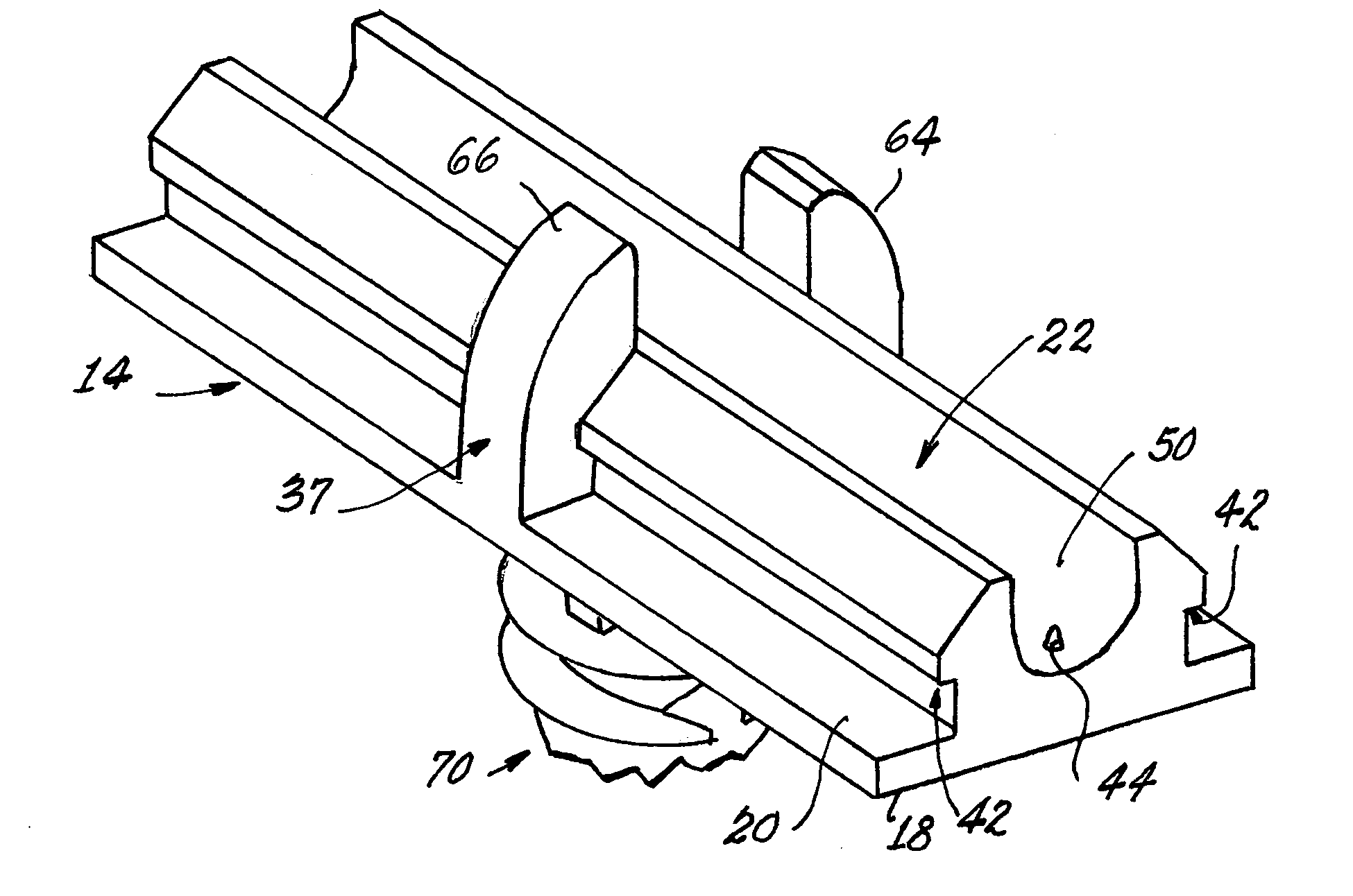
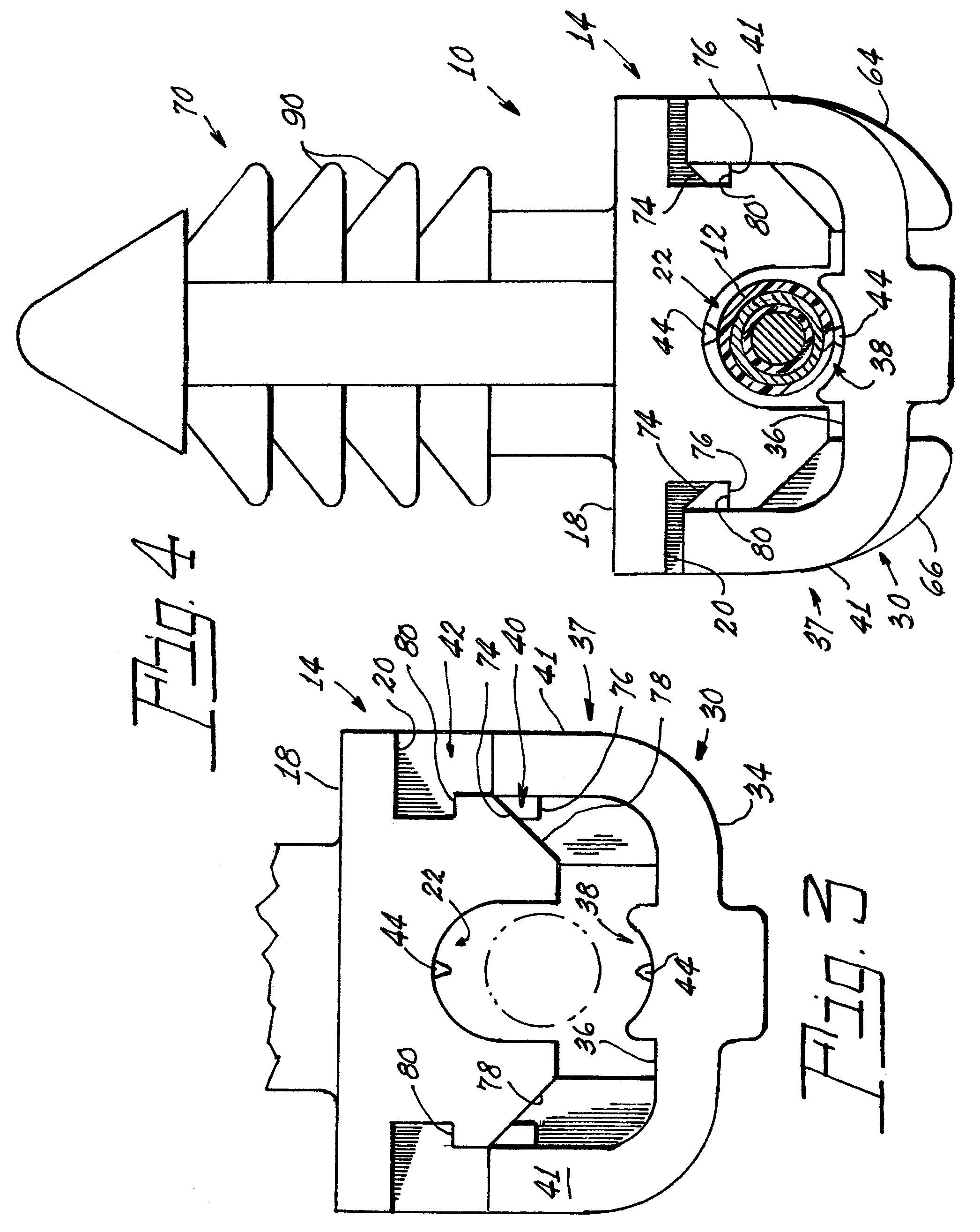
[0014]Referring now to the drawings with greater particularity, a cable retainer 10 for a cable 12 having a longitudinal axis 11 and a given diameter is shown in FIG. 4. A first elongated body half 14 (see FIG. 1) has a first surface 18 and a second, oppositely disposed surface 20. The second oppositely disposed surface 20 has a first cable receiving section 22 therein. The first cable receiving section 22 has a depth at least one half of the given diameter and in a preferred embodiment of the invention takes the form of a groove 50 that is arcuate in cross-section to substantially conform to the configuration of the cable 12.

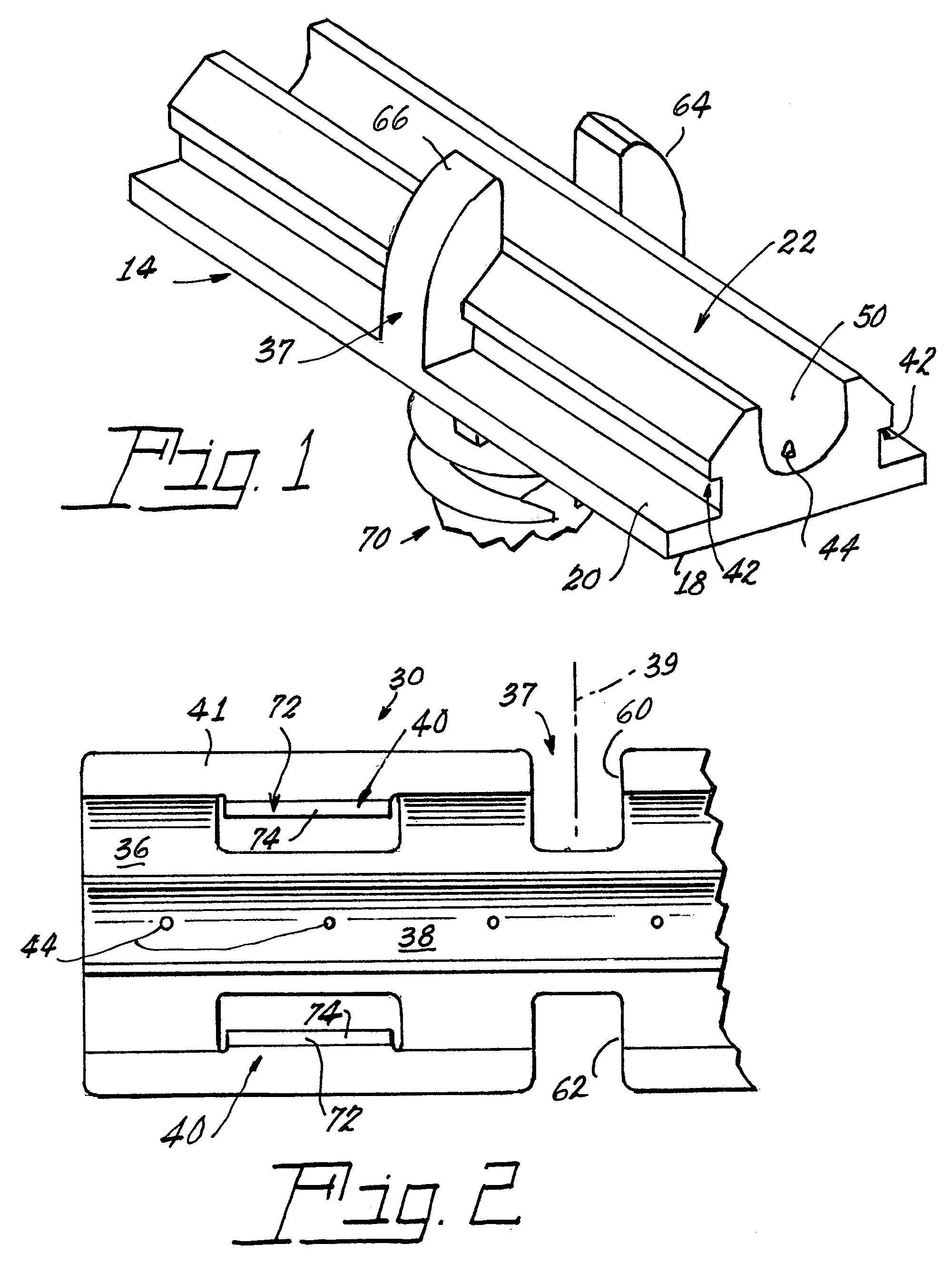
[0015]A second elongated body half 30 (see FIGS. 2 and 3) has a first area 34 and a second, oppositely di...


PUM


Abstract

A cable retainer (10) for a cable (12) having a longitudinal axis (11) and a given diameter has a first elongated body half (14) arrayed along the longitudinal axis (11) and having a first surface (18) and a second, oppositely disposed surface (20), the second oppositely disposed surface (20) having a first cable receiving section (22) therein with a depth at least one half of the given diameter. A second elongated body half (30) is arrayed along the longitudinal axis (11) and has a first area (34) and a second, oppositely disposed area (36) with a second cable receiving section (38) therein. A guide system (37) is provided for orienting the first elongated body half and the second elongated body half A fastener (40) is formed on the second elongated body half (30) and a receptor (42) for the fastener (40) is formed on the first elongated body half (14). A plurality of cable-engaging projections (44) is formed in each of the first cable receiving section (22) and the second cable receiving section (38), the cable engaging projections (44) in the first cable-receiving section (22) being longitudinally displaced from the projections (44) in the second cable receiving section (38), whereby an inserted cable (12) is rendered axially and rotationally stable.

Description

TECHNICAL FIELD[0001]This invention relates to cable locators and more particularly to a cable locator that can be quickly attached to a cable.BACKGROUND ART[0002]Cable locators known in the art usually comprise a soft molded component having a base with a cable locator integrally formed as a part thereof. After proper positioning, the cable locator was attached to a cable by winding tape around the base. This procedure required elaborate jigging stations if the cable employing the cable locators was to be used, for example, as the antenna cable for an automobile. An alternate system is disclosed in U.S. Pat. No. 5,601,262, wherein a cable locator utilizes a two-part connector that includes a base for receiving a cable and a cover for locking the base to the cable. This system had numerous advantages over the taping system, particularly in the speed of applying the locator; however, it has been found that system did not adequately restrain the cable from rotational or longitudinal m...

Claims


Application Information

Patent Timeline
Patent Type & Authority Patents(United States)
IPC IPC(8): F16L3/08
CPCF16L3/10Y10T24/44034
Inventor SWANTNER, MICHAEL J.SEYMOUR, DOUGLAS G.GILLOTTI, RANDALL E.
Owner CARREC INT LTD
Why Eureka
Try Eureka