Floatation system including life raft

a technology of inflatable life rafts and floating systems, which is applied in the direction of floats, aircraft ejection means, rafts, etc., can solve the problems of less efficient trips to and from offshore platforms, the space that must be allocated to stow the raft, and the space that must be allocated to the inflatable life ra

Inactive Publication Date: 2006-10-03
APICAL INDS +1
View PDF10 Cites 20 Cited by
  • Summary
  • Abstract
  • Description
  • Claims
  • Application Information

AI Technical Summary

Problems solved by technology

On the other hand, inflatable emergency rafts are conventionally stored inside the helicopter fuselage, which is disadvantageous for several reasons.
One disadvantage of storing the inflatable raft inside the aircraft is the amount of space that must be allocated to stow the raft.
Inflatable rafts of this sort commonly take up more than six cubic feet of space when deflated.
Since six cubic feet is the approximate equivalent of two extra passengers, trips to and from an offshore platform, for example, are far less efficient when an inflatable life raft is stowed within the aircraft fuselage.
A further disadvantage of storing the inflatable raft inside the aircraft is that the raft must be manually expelled from the aircraft before being inflated, which wastes precious time and may be more difficult if the aircraft is damaged or the passengers are injured.
Yet another disadvantage is that some on-board raft systems require significant modification of the aircraft fuselage, (e.g., additional compartment and door) which is very costly.

Method used


Image

  • Floatation system including life raft
  • Floatation system including life raft
  • Floatation system including life raft

Examples


Embodiment Construction

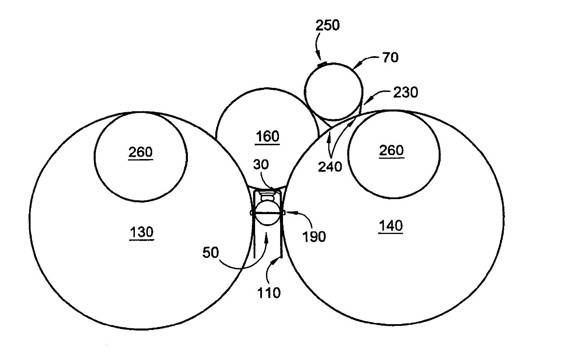
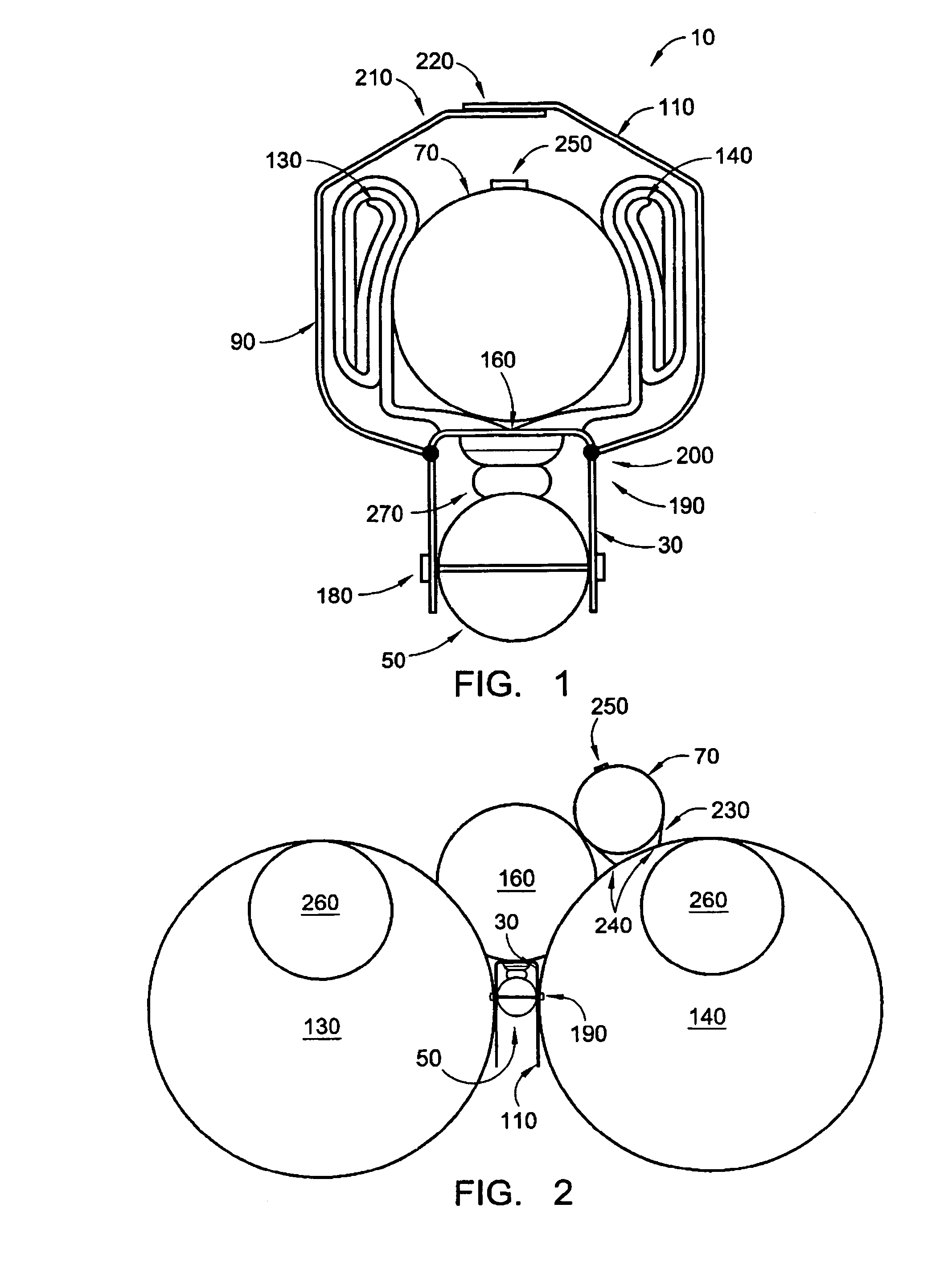
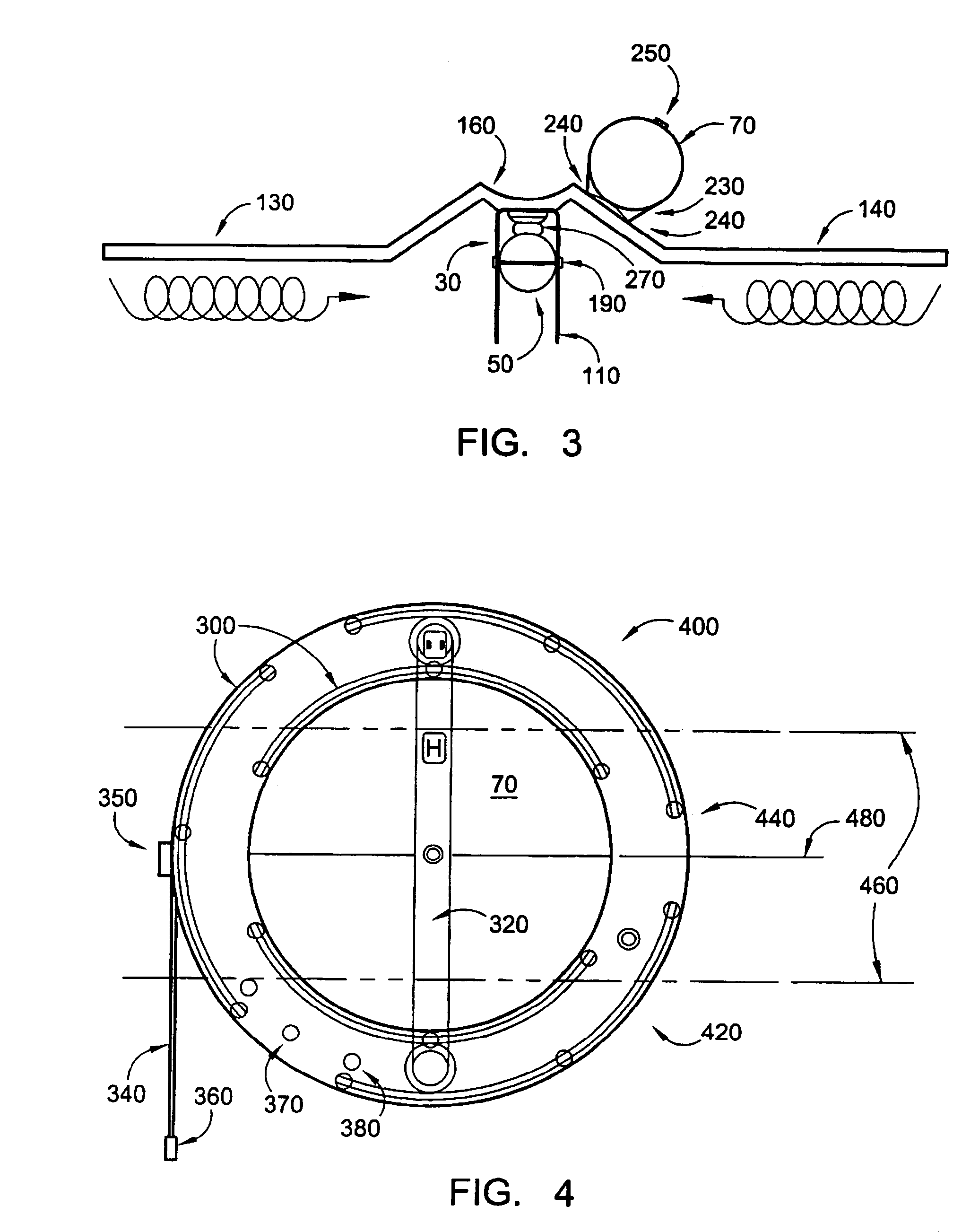
[0021]Referring to FIGS. 1–4 and 8, an emergency floatation system 10 according to the present invention is generally comprised of a girt member 30 for attachment to a landing skid 50 of an aircraft such as a helicopter 60, an emergency life raft 70, a float system 90 and a flexible cover 110. In the preferred embodiment depicted in FIGS. 1–3, the float system 90 includes a pair of large side floats 130,140 connected by a smaller center float 160. As one of ordinary skill in the art can appreciate, the float system 90 may consist of any number of alternative float arrangements that utilize any number of individual floats.

[0022]Importantly, the floatation system 10 has three different configurations consisting of: (1) a packed configuration as depicted in FIG. 1; (2) a partially deployed configuration as depicted in FIG. 2, wherein the float system 90 has been fully deployed, but the raft 70 remains fully packed; and (3) a fully deployed configuration, which incorporates both the flo...


PUM


Abstract

A floatation system for attachment to a helicopter landing skid includes a girt dimensioned to be attached to a landing skid and a plurality of floats attached to the elongate girt, wherein the plurality of floats are adapted to be converted from a packed configuration to an deployed configuration, and wherein at least one of the plurality of floats extends beneath the elongate girt when the plurality of floats is in the deployed configuration.

Description

CROSS REFERENCE TO RELATED APPLICATIONS[0001]This application is a continuation of U.S. patent application Ser. No. 09 / 961,787, filed on Sep. 21, 2001 now U.S. Pat. No. 6,709,305.FIELD OF THE INVENTION[0002]The present invention is directed to emergency floatation devices, in general, and more particularly to emergency floatation devices used during and after emergency landings.BACKGROUND OF THE INVENTION[0003]The use of floatation devices for buoyantly supporting an aircraft on a body of water has been prevalent for many years. Part-time and full-time fixed floatation systems have been in widespread use for many years. Some aircraft, especially helicopters, are equipped with both inflatable floatation bags and an inflatable life raft. Typically, deflated floatation bags are fixedly attached to the helicopter landing skids and packed tightly within flexible fabric covers. These floatation bags are inflated in order to support the helicopter when ditching or landing in water is antic...

Claims


Application Information

Patent Timeline
Patent Type & Authority Patents(United States)
IPC IPC(8): B63B35/58B63C9/23B64C25/56
CPCB64C25/56B64D25/18B64C2025/325
Inventor PARROTT, DAVID G.HITZFIELD, DON V.
Owner APICAL INDS
Why Eureka
Try Eureka