Socket structure and method for forming the same

a socket and socket technology, applied in the field of sockets, can solve the problems of unstable socket structure, limited electrical connection, and inconvenience in assembling and separation between the socket and the plug,

Active Publication Date: 2006-10-10
DELTA ELECTRONICS INC
View PDF11 Cites 18 Cited by
  • Summary
  • Abstract
  • Description
  • Claims
  • Application Information

AI Technical Summary

Benefits of technology

[0025]In accordance with another aspect of the present invention, a method for forming a socket having a main body, a conducting piece having an opening mounted thereon, and at least a terminal comprising a central pillar having a first end and a second end, a first ring mounted on the central pillar and having a first surface and a second surface, and a second ring mounted on the central pillar and having a third surface and a fourth surface, wherein the second surface and the third surface are adjacent to each other and have a distance therebetween includes steps of providing the at lest a terminal, injection molding the main body for surrounding the first ring and the second ring and filling the distance between the second surface and the third surface, sleeving the conducting piece on the second end of the terminal through the opening so as to contact the conducting piece with the fourth surface of the second ring, riveting the second end of the terminal for tightly rejecting or biasing the conducting piece against the s

Problems solved by technology

However, it is obvious that the contact area of the circular contact 40 in the conventional socket structure is limited so that the electrical connection is therefore limited, too.
In addition, because the terminal 12 is loosed, the assembling and separation between the socket and the plug will become a difficult job and the contact between the terminal 12 and the conducting piece 13 will also become a loosed contact which can not always keep in contact so as to cause an unstable power supply.
Hence, it is obvious t

Method used


Image

  • Socket structure and method for forming the same
  • Socket structure and method for forming the same
  • Socket structure and method for forming the same

Examples


Embodiment Construction

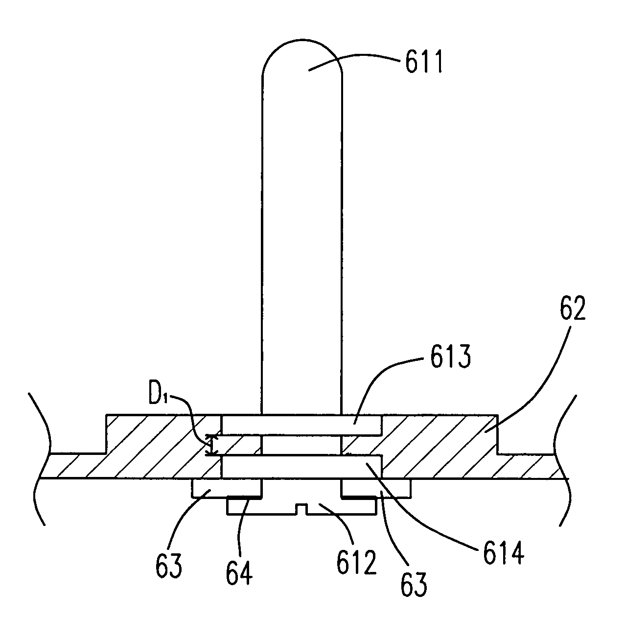
[0039]It is an object of the present invention to provide a socket structure whose fixity among all elements will not be easily loosed for extending the usage life thereof and a method for forming the same.

[0040]It is another object of the present invention to provide a socket structure which can increase the contact area between a terminal and a conducting piece for maintaining a stable power supply.

[0041]It is another further object of the present invention to provide a socket structure which can reduce a melt phenomenon of a plastic main body due to the heat produced during operation so as to maintain a stable socket structure.

[0042]The present invention will now be described more specifically with reference to the following embodiments. It is to be noted that the following descriptions of preferred embodiments of this invention are presented herein for purpose of illustration and description only; it is not intended to be exhaustive or to be limited to the precise form disclosed...


PUM


Abstract

A socket and a method for forming the same are provided. The socket includes a main body, at least a terminal mounted on the main body, wherein the terminal includes a central pillar having a first end and a second end, a first ring mounted on the central pillar and having a first surface and a second surface, and a second ring mounted on the central pillar and having a third surface and a fourth surface, wherein the second surface and the third surface are adjacent to each other and have a distance therebetween, and at least a conducting piece having an opening mounted thereon for being sleeved on the second end of the central pillar and directly and electrically connected with the second ring.

Description

FIELD OF THE INVENTION[0001]This invention relates to a socket and a method for forming the same, and more particular to a socket which has a better conductivity and safety and a method for forming the same.BACKGROUND OF THE INVENTION[0002]Please refer to FIG. 1 which illustrates a three-dimensional view of a socket structure in the prior arts, and FIGS. 2A˜2B which illustrate a front view and a back view of the socket structure in the prior arts. As shown in these figures a socket 1 includes a plastic main body 10 having an indentation 11 and two terminals 12 mounted in the indentation 11, wherein the two terminals 12 are employed to be connected with a corresponding plug (not shown), and furthermore, the two terminals 12 are respectively and directly contacted with a conducting piece 13, as shown in FIG. 2B.[0003]Please refer to FIG. 3 which illustrates a structural view of a terminal of a conventional socket. As shown in FIG. 3, in the conventional socket, a terminal 12 includes ...

Claims


Application Information

Patent Timeline
IPC IPC(8): H01R13/405H01R4/18H01R4/06
CPCH01R13/405H01R4/06
Inventor CHEN, CHUN-CHEN
Owner DELTA ELECTRONICS INC
Why Eureka
Try Eureka