Test tube holder

a test tube and holder technology, applied in the field of test tube holders, can solve the problems that the column rack or the test tube holder cannot be applied to a test tube of a size (especially the outside diameter) different from that of the specific test tub

Active Publication Date: 2006-10-17
IDS CO LTD
View PDF2 Cites 64 Cited by
  • Summary
  • Abstract
  • Description
  • Claims
  • Application Information

AI Technical Summary

Benefits of technology

[0007]An object of the present invention is to provide a versatile test tube holder that is applicable to a plurality of test tubes having different outside diameters.

Problems solved by technology

Therefore, the columnar rack or the test tube holder cannot be applied to a test tube of size (especially the outside diameter) different from that of the specific test tube.

Method used


Image

  • Test tube holder
  • Test tube holder
  • Test tube holder

Examples


first embodiment

(First Embodiment)

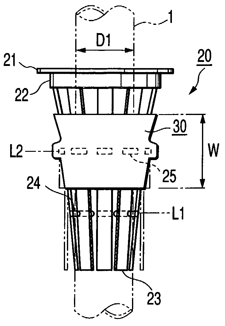
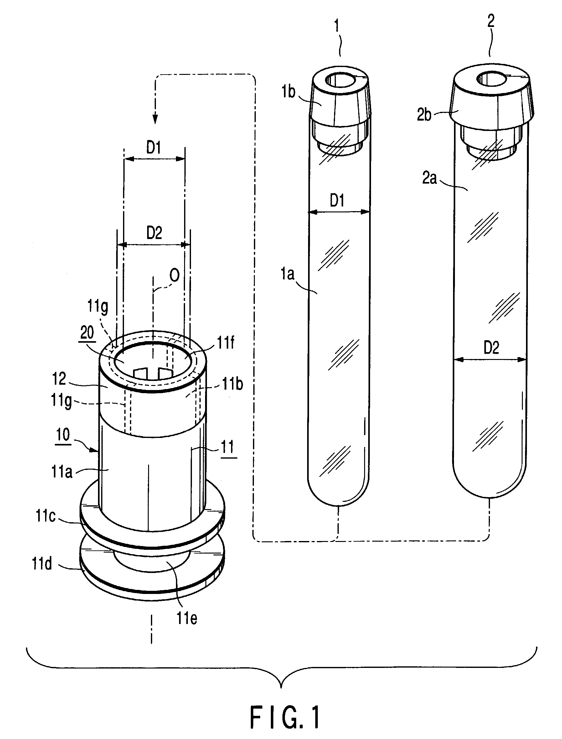
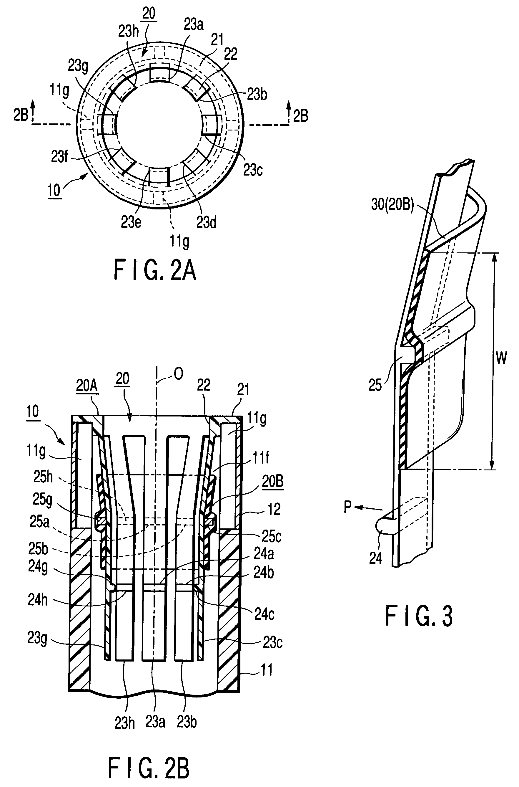
[0027]FIG. 1 shows a test tube holder according to a first embodiment of the present invention. The test tube holder includes a holder body 10 and a test tube insertion adapter 20 fitted into the holder body 10. Even though any one of a plurality of test tubes having different outside diameters (two test tubes 1 and 2 having different outside diameters D1 and D2 in the first embodiment) is inserted into the test tube holder, the adapter 20 can hold the inserted test tube with stability. The test tubes 1 and 2 include tube bodies 1a and 2a, respectively, and the openings of the tube bodies 1a and 2a are closed with caps 1b and 2b, respectively.

[0028]The holder body 10 includes engagement sections (two flange sections 11c and 11d in the first embodiment), which are to be engaged with conveying guide rails (not shown), on the outer surface of a proximal end portion (a lower end portion in FIG. 1) of a columnar base body 11 that is made of, e.g., synthetic resin. The h...

second embodiment

(Second Embodiment)

[0038]FIG. 5A is a partial side view showing a structure of a main part of a test tube insertion adapter of a test tube holder according to a second embodiment of the present invention. FIG. 5B is a cross-sectional view taken along line 5B—5B of FIG. 5A. The second embodiment differs from the first embodiment in that projections 26 (26a to 26c) each having a stopping lug are provided on the respective surfaces of flat spring sections 23 (23a to 23c) fitted into a fitting holes 41 (41a to 41c) formed in a rubber band 40 for binding the flat spring sections. With this structure, the projections 26 (26a to 26c) reliably stop the fitting holes 41 (41a to 41c). Therefore, even though an adapter body 20A is vibrated, the rubber band 40 does not slip down from the flat spring sections 23 (23a to 23c). Since the second embodiment is the same as the first embodiment except for the above, its detailed descriptions are omitted.

third embodiment

(Third Embodiment)

[0039]FIG. 6A is a partial side view showing a structure of a main part of a test tube insertion adapter of a test tube holder according to a third embodiment of the present invention. FIG. 6B is a cross-sectional view taken along line 5B—5B of FIG. 5A. The third embodiment differs from the second embodiment in that hooks 51 (51a to 51c) provided on a rubber band 50 for binding flat spring sections 23 (23a to 23c) are hooked on projections 26 (26a to 26c) each having a stopping lug. With this structure, the projections 26 (26a to 26c) reliably stop the hooks 51 (51a to 51c). Therefore, even though an adapter body 20A is vibrated, the rubber band 50 does not slip down from the flat spring sections 23 (23a to 23c). According to the third embodiment, the rubber band 50 can be removed relatively easily when it is replaced with a new one. Since the third embodiment is the same as the second embodiment except for the above, its detailed descriptions are omitted.


PUM

PropertyMeasurementUnit
diametersaaaaaaaaaa
circumferenceaaaaaaaaaa
pressureaaaaaaaaaa

Abstract

A test tube holder includes a test tube insertion adapter having an adapter body and an elastic annular band and projections. The adapter body includes a flange section, an annular section, a plurality of flat spring sections whose proximal end portions are connected to the annular section and whose distal end portions extend inward in the cylindrical hollow and bent toward the axis of the adapter body and contact sections which are formed on the inner surfaces of the flat spring sections. The elastic annular band designed to bind the flat spring sections together while surrounding the outer surfaces thereof over a given range in order to bring the contact sections into contact with the outer surfaces of the test tubes. The projections projected from the outer surfaces of the flat spring sections to hold the elastic annular band in a given position.

Description

CROSS-REFERENCE TO RELATED APPLICATIONS[0001]This application is based upon and claims the benefit of priority from the prior Japanese Patent Application No. 2002-054203, filed Feb. 28, 2002, the entire contents of which are incorporated herein by reference.BACKGROUND OF THE INVENTION[0002]1. Field of the Invention[0003]The present invention relates to a test tube holder that is capable of holding a test tube, which keeps a specimen such as blood, in an upright position and is suitable for conveying the test tube.[0004]2. Description of the Related Art[0005]Conventionally test tube holders called columnar racks have been used a lot. The columnar racks each have a columnar base body made of synthetic resin. An engagement groove with which a guide rail of a conveyor belt is engaged and a control groove for controlling the conveyance of a test tube by the conveyor belt are formed on the outer surface of a proximal end portion of the columnar base body such that the test tube can easily...

Claims


Application Information

Patent Timeline
Patent Type & Authority Patents(United States)
IPC IPC(8): B01L9/06B65D85/42G01N35/04
CPCB01L9/06B01L2200/023
Inventor ITOH, TERUAKI
Owner IDS CO LTD
Why Eureka
Try Eureka