
Adjustable tool handle for paint rollers and the like

a tool handle and roller technology, applied in the field of handle improvement, can solve the problems of user fatigue, unwanted strain, and limit the use of the handle for other applications, and achieve the effect of improving the use effect of the handl

Active Publication Date: 2006-10-24
NICOLAY FAMILY ENTERPRISES
View PDF56 Cites 21 Cited by
  • Summary
  • Abstract
  • Description
  • Claims
  • Application Information

AI Technical Summary

Benefits of technology

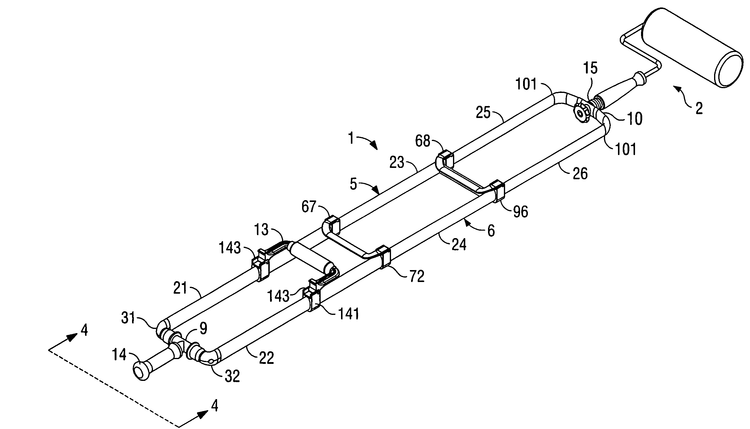
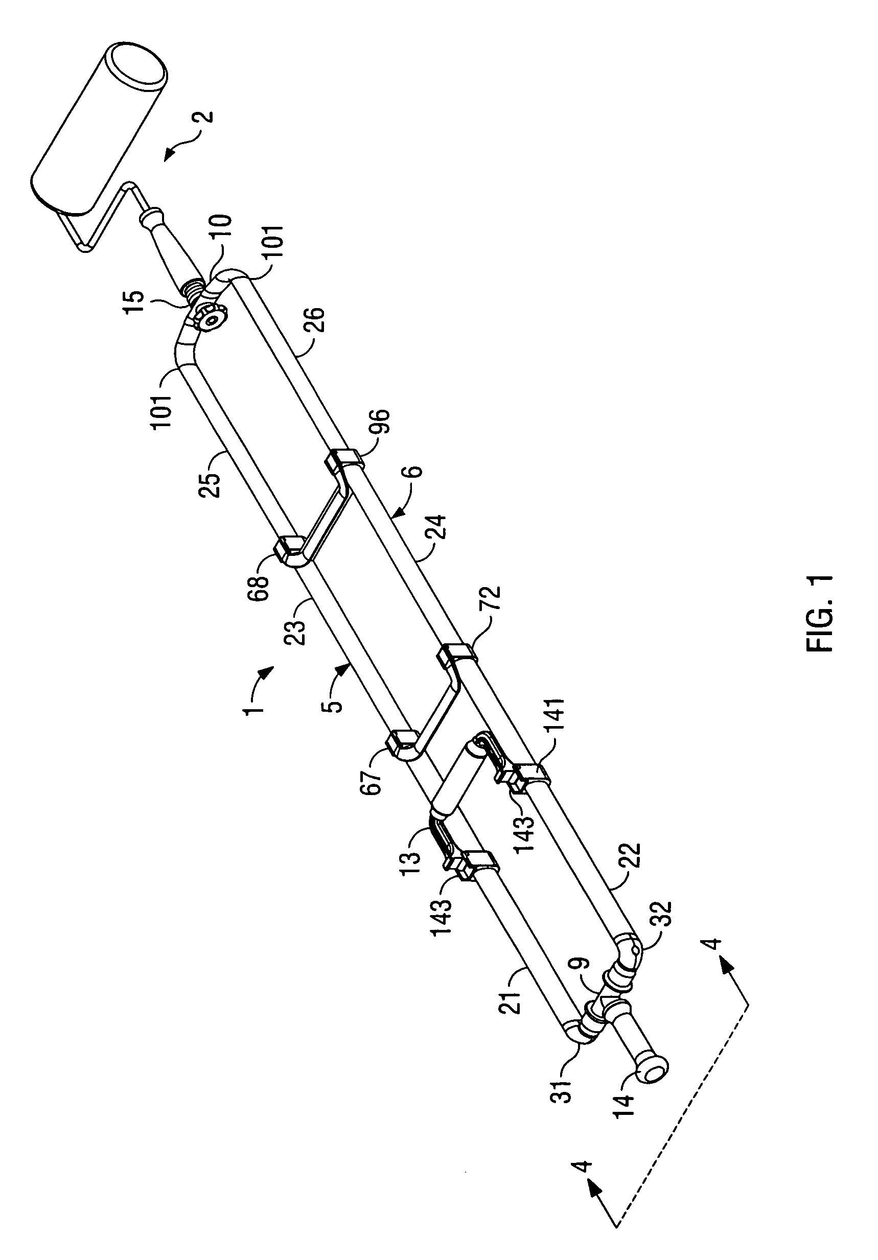
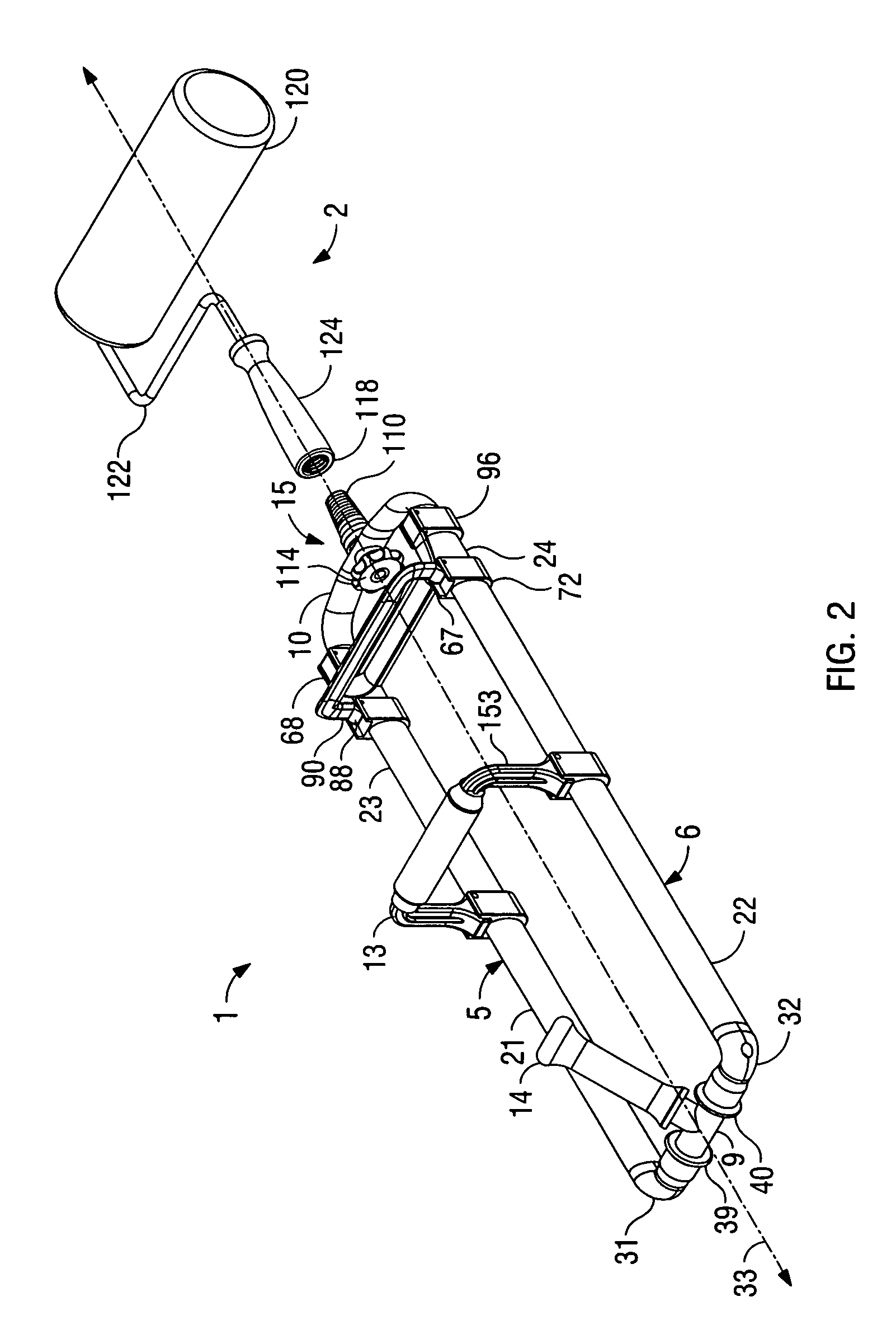
"The present invention is a tool handle assembly that can be connected to different tool heads. It includes a leg assembly with a first and second end, an outer grip handle, an inner grip handle, and a tool head connector. The outer grip handle pivots around a perpendicular axis, while the inner grip handle pivots between a storage position and an operating position. The inner grip handle can also be slidably mounted on the leg assembly. The tool head connector allows for the use of one tool handle with multiple tool heads. The leg assembly is telescopic and consists of two parallel extending legs connected by cross-members. The technical effect of this invention is a versatile tool handle assembly that can be easily connected to different tool heads, making it more efficient and flexible in use."

Problems solved by technology

Although simple to manufacture, the conventional single, straight shaft tool handle must be gripped in a manner that is often awkward or uncomfortable for the user resulting in unwanted strain and causing pre-mature, user fatigue.
Although the selected configuration may facilitate use of the tool handle for a specific application, the fixed configuration limits use of the handle for other applications and does not permit the user to modify the handle configuration to accommodate the manner in which they might prefer to grip the tool depending upon the application for which it is to be utilized.

Method used


Image

  • Adjustable tool handle for paint rollers and the like
  • Adjustable tool handle for paint rollers and the like
  • Adjustable tool handle for paint rollers and the like

Examples


Embodiment Construction

[0016]As required, detailed embodiments of the present invention are disclosed herein; however, it is to be understood that the disclosed embodiments are merely exemplary of the invention, which may be embodied in various forms. Therefore, specific structural and functional details disclosed herein are not to be interpreted as limiting, but merely as a basis for the claims and as a representative basis for teaching one skilled in the art to variously employ the present invention in virtually any appropriately detailed structure. The drawings constitute a part of this specification and include exemplary embodiments of the present invention and illustrate various objects and features thereof.

[0017]Certain terminology will be used in the following description for convenience in reference only and will not be limiting. For example, the words “upwardly,”“downwardly,”“rightwardly,” and “leftwardly” will refer to directions in the drawings to which reference is made. The words “inwardly” a...


PUM


Abstract

A tool handle assembly adapted to be connected to a tool head comprises a leg with an inner grip handle connected to the leg between first and second ends thereof, an outer grip handle connected to the first end of the leg and a tool head connector connected to the second end of the leg. The inner grip handle includes a grip extending perpendicular to the leg. The outer grip handle preferably pivots about an axis extending perpendicular to an axis extending through the leg. The inner grip handle is preferably pivotal between a storage and use position and is slidably connected to the leg. The leg of the tool handle preferably telescopes and comprises a pair of parallel extending legs connected together by cross-members.

Description

BACKGROUND OF THE INVENTION[0001]1. Field of the Invention[0002]This invention relates to an improved handle for use on tools such as paint rollers, brooms, rakes, hoes, mops and the like.[0003]2. Description of the Related Art[0004]In U.S. Pat. No. 6,592,160, an improved tool handle was disclosed which was particularly well adapted for use in association with shovels. The present invention is directed to further improvements to such a tool handle for tools which are used by employing a sweeping type motion such as brooms, paint rollers, mops, rakes and hoes. Such tools typically have handles comprising a single straight shaft which is secured to a head of the tool along a central axis of the tool head.[0005]Although simple to manufacture, the conventional single, straight shaft tool handle must be gripped in a manner that is often awkward or uncomfortable for the user resulting in unwanted strain and causing pre-mature, user fatigue. Tool handles have been manufactured which are cu...

Claims


Application Information

Patent Timeline
Patent Type & Authority Patents(United States)
IPC IPC(8): A45C3/00A45F5/00B05C17/02B25G1/06B25G1/10
CPCA45F5/00B05C17/0205B25G1/102B25G1/06Y10T16/498
Inventor NICOLAY, KENNETH M.MENDELSON, LEWIS A.GUERRA, LAWRENCE E.
Owner NICOLAY FAMILY ENTERPRISES
Learn More