Shotgun cleaning shell device

a cleaning device and shotgun technology, applied in the field of disposable cleaning devices, can solve the problems of no solution for cleaning residue, most shotgun owners (%) do not clean shotguns at all, etc., and achieve the effects of preventing long-term exposure, preventing long-term exposure, and ensuring the cleaning

Inactive Publication Date: 2006-11-07
NAFZIGER MICHAEL
View PDF8 Cites 19 Cited by
  • Summary
  • Abstract
  • Description
  • Claims
  • Application Information

AI Technical Summary

Benefits of technology

[0013]The present invention may be readily adapted to a variety of shotgun bore sizes. Embodiments of the present invention may provide, among other benefits: a safe, quick, easy, disposable and effective way to clean a shotgun bore. It also prevents long term exposure to petroleum distillates (gun bore cleaning solvents) and for those that are sensitive or hyper-sensitized to solvents a method for using gun bore solvents quickly with minimum exposure. This device will save the user significant time in cleaning and maintaining their shotgun without having to sacrifice the effectiveness of cleaning the shotgun bore by hand. Also, because this device uses a very low energy propellant it is much safer than many of the other shotgun shell cleaning devices on the market. Many collectors of shotguns have large inventories that must be maintained and in high humidity climates (most of the United States) these collections need to receive frequent gun oil treatments. This device facilitates a swift method of easily treating these collections and inventories with moisture barrier gun oil.

Problems solved by technology

Because of the inconvenience and time required to clean a shotgun, most shotgun owners (as much as 80%) do not clean their shotguns at all.
These various methods, however, tend to force the cleaning materials and solutions through the bore so quickly that the solutions do not have time to act on the residue in the bore.
Additionally, many of the previous methods use “gun powder” to propel the cleaning devices, thereby causing the bore to be contaminated with gun powder residue defeating the purpose of the cleaning method.
The methods also may potentially cause injury as cleaning materials are shot out of the bore at a high rate of speed.

Method used


Image

  • Shotgun cleaning shell device
  • Shotgun cleaning shell device
  • Shotgun cleaning shell device

Examples


Embodiment Construction

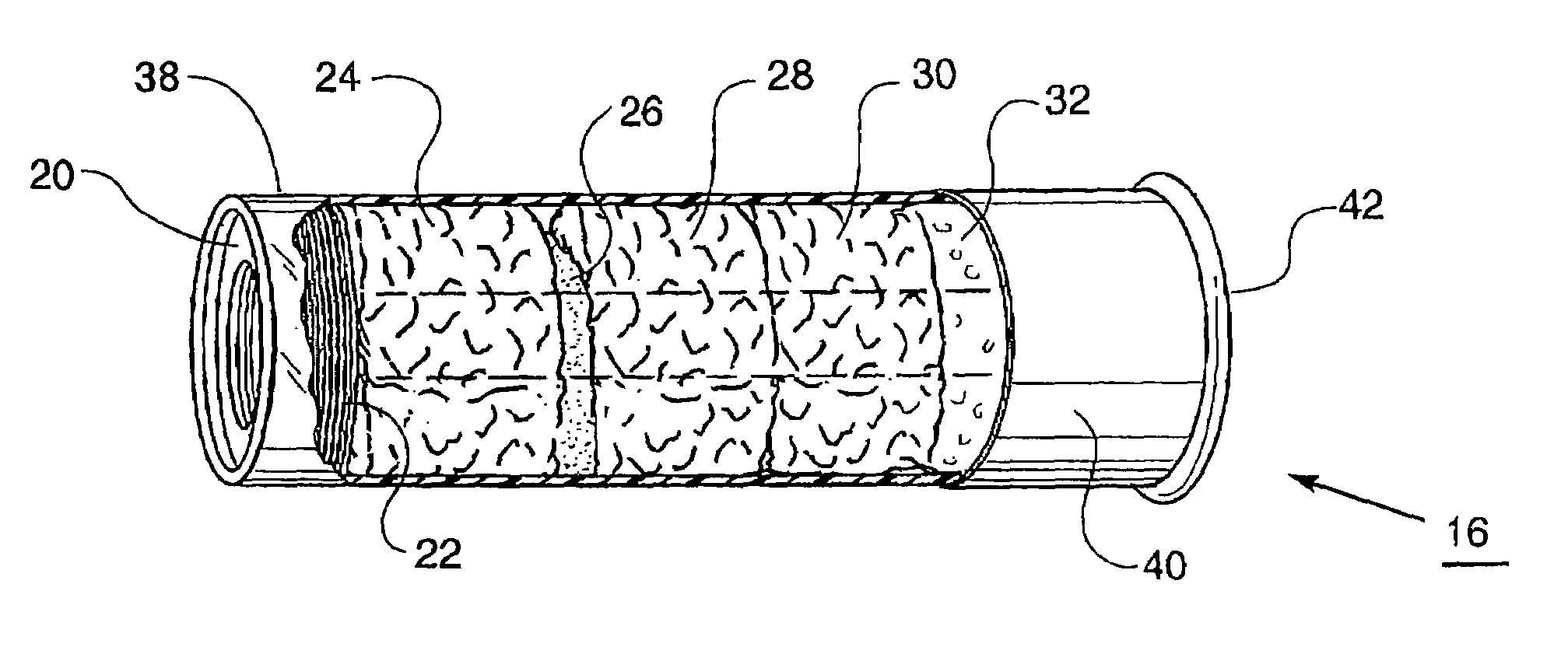
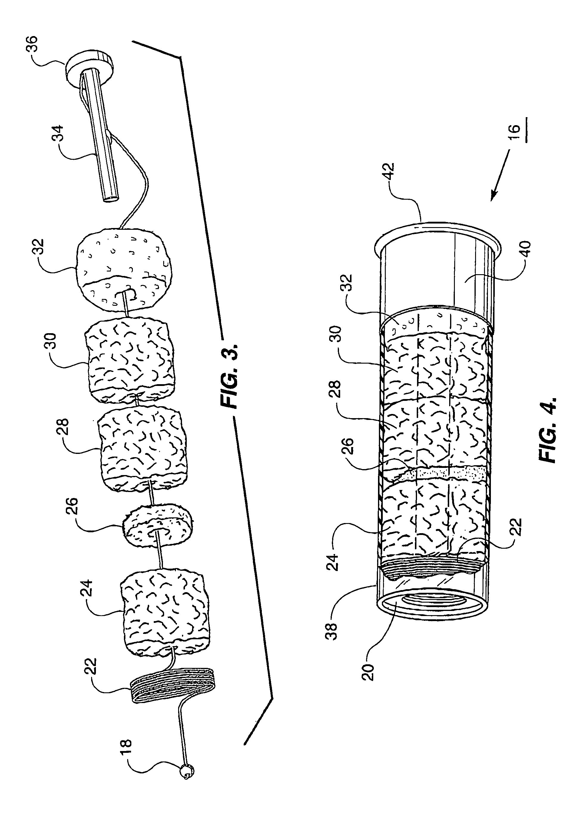
[0022]As discussed above, embodiments of the present invention relate to a disposable shotgun cleaning shell device. Generally, a shotgun cleaning shell device configured according to an embodiment of the present invention consists of a shotgun shell case which contains at least one cleaning member such as a solvent cleaning wad connected by a cord to a bead. When a propellant device propels the bead out of a bore of a shotgun, the at least one cleaning member may then be pulled by the cord through the bore of the shotgun.

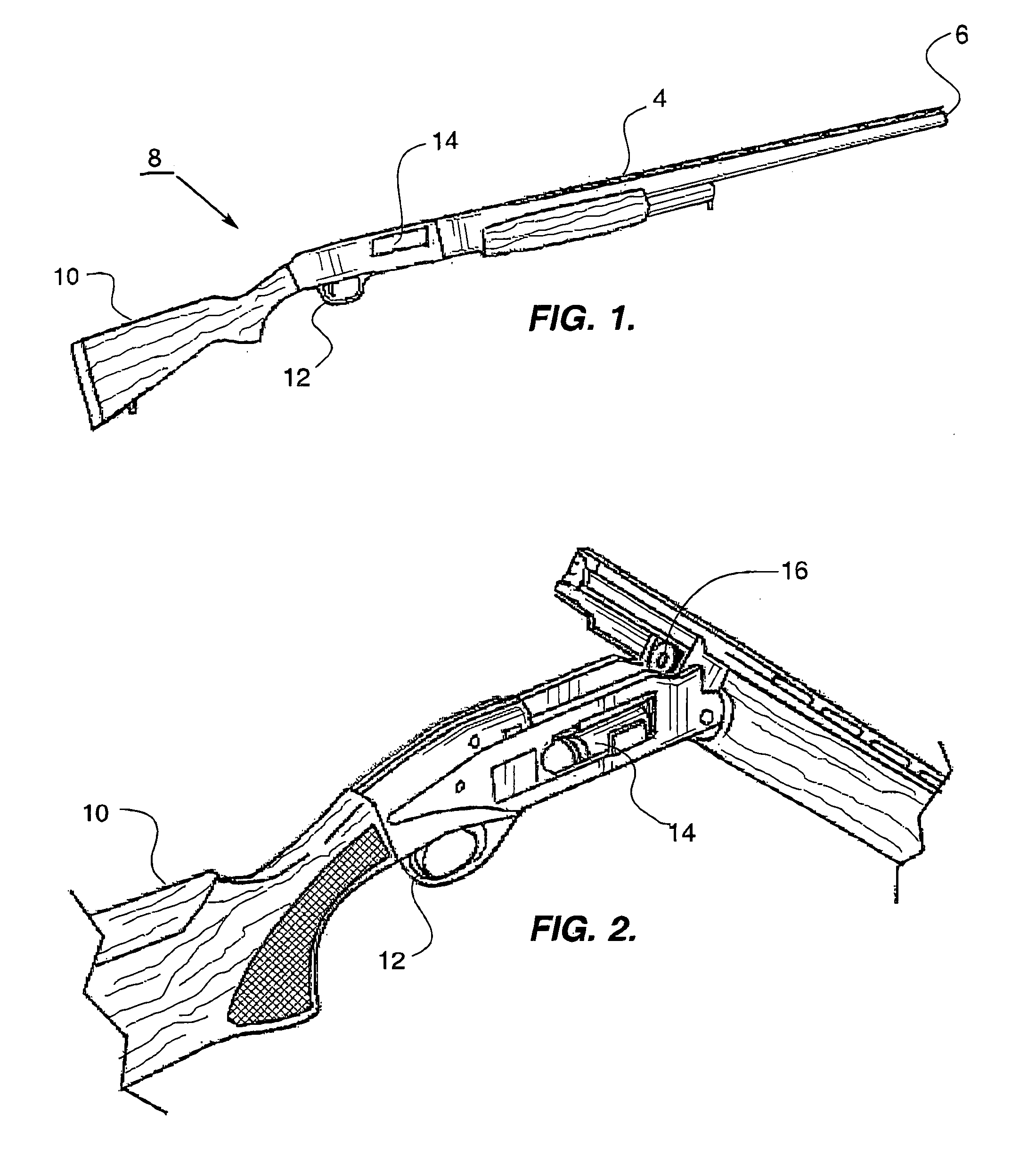
[0023]FIG. 1 depicts a standard configuration of a shotgun 8. A standard shotgun 8 consists of a stock 10 which is the part of the shotgun 8 that a user grasps to support the shotgun 8 while in use. A trigger 12 is used to fire a shotgun 8 shell. A blast from a shell and shot travel down the inside of the shotgun's 8 barrel 4 along a bore 6. A spent shell is ejected from an ejection port 14 typically located in a side of the shotgun 8.

[0024]FIG. 2 depicts a standar...


PUM


Abstract

A Shotgun Cleaning Shell for cleaning the bore of a shotgun, wherein the shell comprises: a cylindrical shell case, a head connected to an end of the case, a seal connected to the other end of the case, a bead contained within the case, a cord wherein an end of the cord is connected to the bead, at least one cleaning member connected to the cord, a squeegee connected to the other end of the cord, a tubular member connected to the squeegee and wherein the bead is contiguous the other end of the tubular member, a propellant device attached to the head and within the tubular member, wherein, the propellant device propels the bead through a bore of a shotgun, the bead exiting the bore, and wherein a user can propel the at least one cleaning member and the squeegee along the bore of the shotgun.

Description

BACKGROUND OF THE INVENTION[0001]1. Technical Field[0002]This invention relates to a disposable cleaning device for use in shotguns which fits inside a standard shotgun shell casing that mimics traditional cleaning methods and allows the user to simply fire the gun and slowly pull on a cord in order to clean a shotgun bore.[0003]2. Background Art[0004]The use of shotguns is very popular in the United States and abroad. Shotguns, however, like all other guns require regular cleaning in order to keep the gun in the best condition possible. In fact, a shotgun must be cleaned after each use. One of the main areas of shotgun which requires regular cleaning is the bore.[0005]Because of the inconvenience and time required to clean a shotgun, most shotgun owners (as much as 80%) do not clean their shotguns at all.[0006]Currently, there are several basic types of bore cleaning systems known in the art. The first is the most commonly known and most traditional method of using a cleaning “kit”...

Claims


Application Information

Patent Timeline
Patent Type & Authority Patents(United States)
IPC IPC(8): F42B8/00
CPCF42B5/24
Inventor NAFZIGER, MICHAEL
Owner NAFZIGER MICHAEL
Why Eureka
Try Eureka