Atomizing device

a technology of atomizer and atomizer, which is applied in the direction of inhalators, other medical devices, tobacco, etc., can solve the problem that the amount of inhaled amount of a released matter such as a flavor or a medical agent cannot be controlled accurately

Inactive Publication Date: 2006-11-07
SEIKO EPSON CORP
View PDF8 Cites 170 Cited by
  • Summary
  • Abstract
  • Description
  • Claims
  • Application Information

AI Technical Summary

Benefits of technology

[0011]Further, since the fluid jet system (for example, inkjet system) is adopted for the discharging means, the target amount of droplets can be discharged from the discharging means accurately and reliably. Thereby, the liquid matter can be atomized accurately and reliably to the target amount.
[0030]In this way, by attaching the cartridge to the mounted portion of the casing, the liquid matter is supplied from its storage part to the discharging means, and, by detaching the cartridge from the mounted portion of the casing, the supply of the liquid matter from its storage part to the discharging means is stopped.

Problems solved by technology

However, by various types of conventional atomizing devices, the released amount (inhaled amount) of a released matter such as a flavor or a medical agent can not be controlled accurately.

Method used


Image

  • Atomizing device
  • Atomizing device
  • Atomizing device

Examples


first embodiment

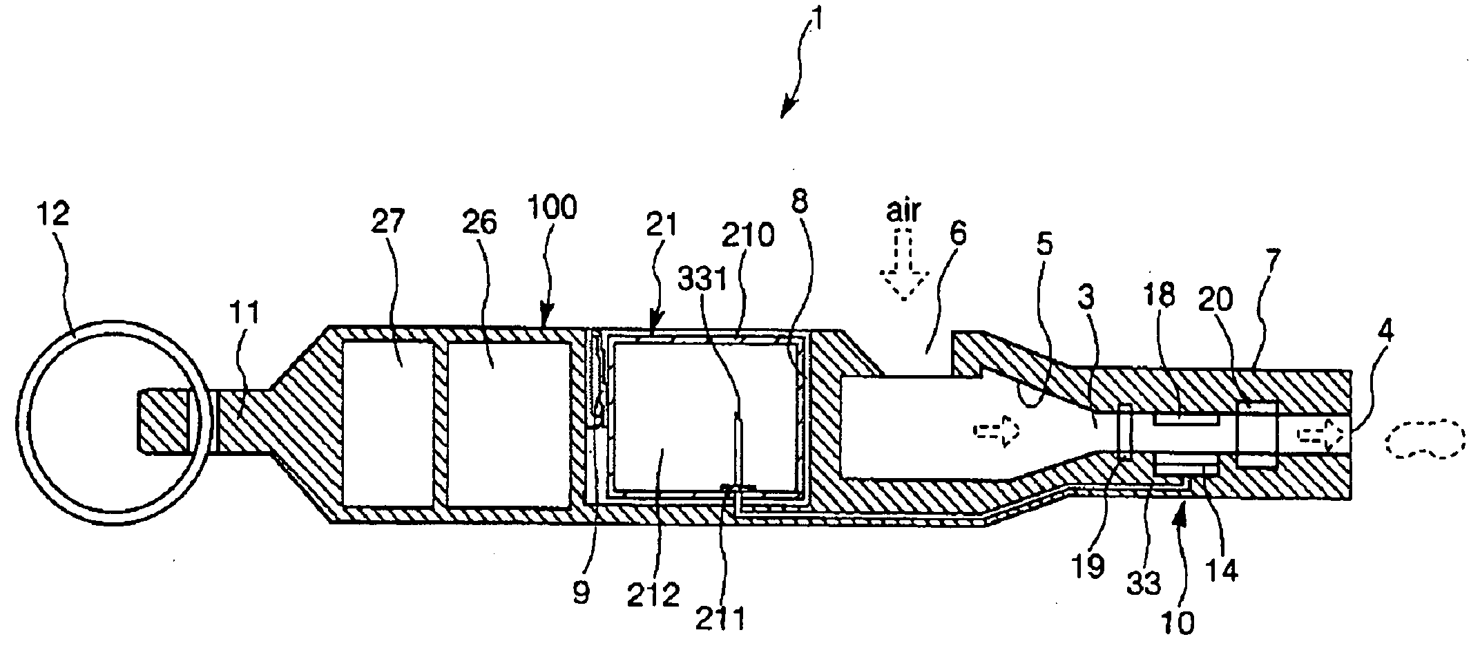
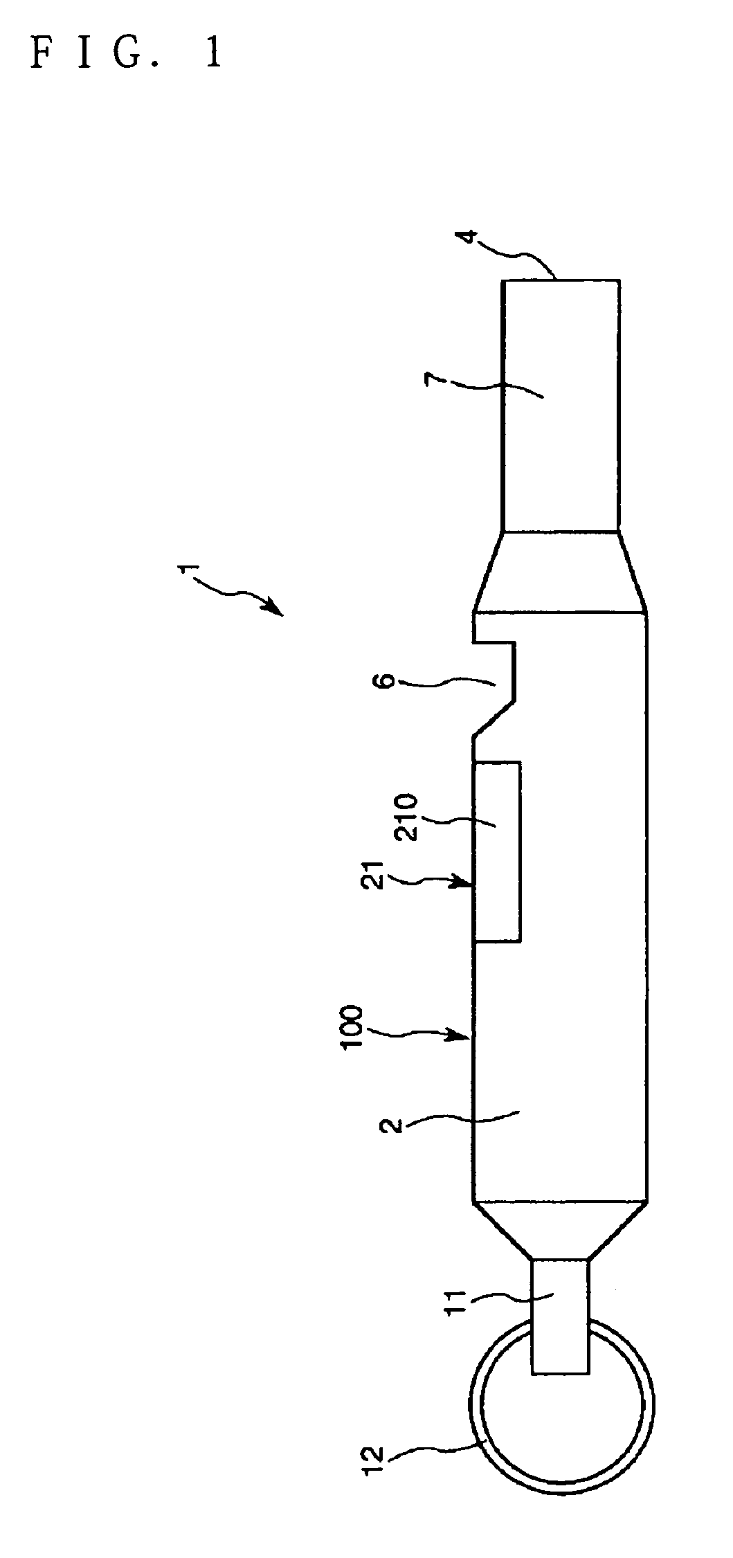
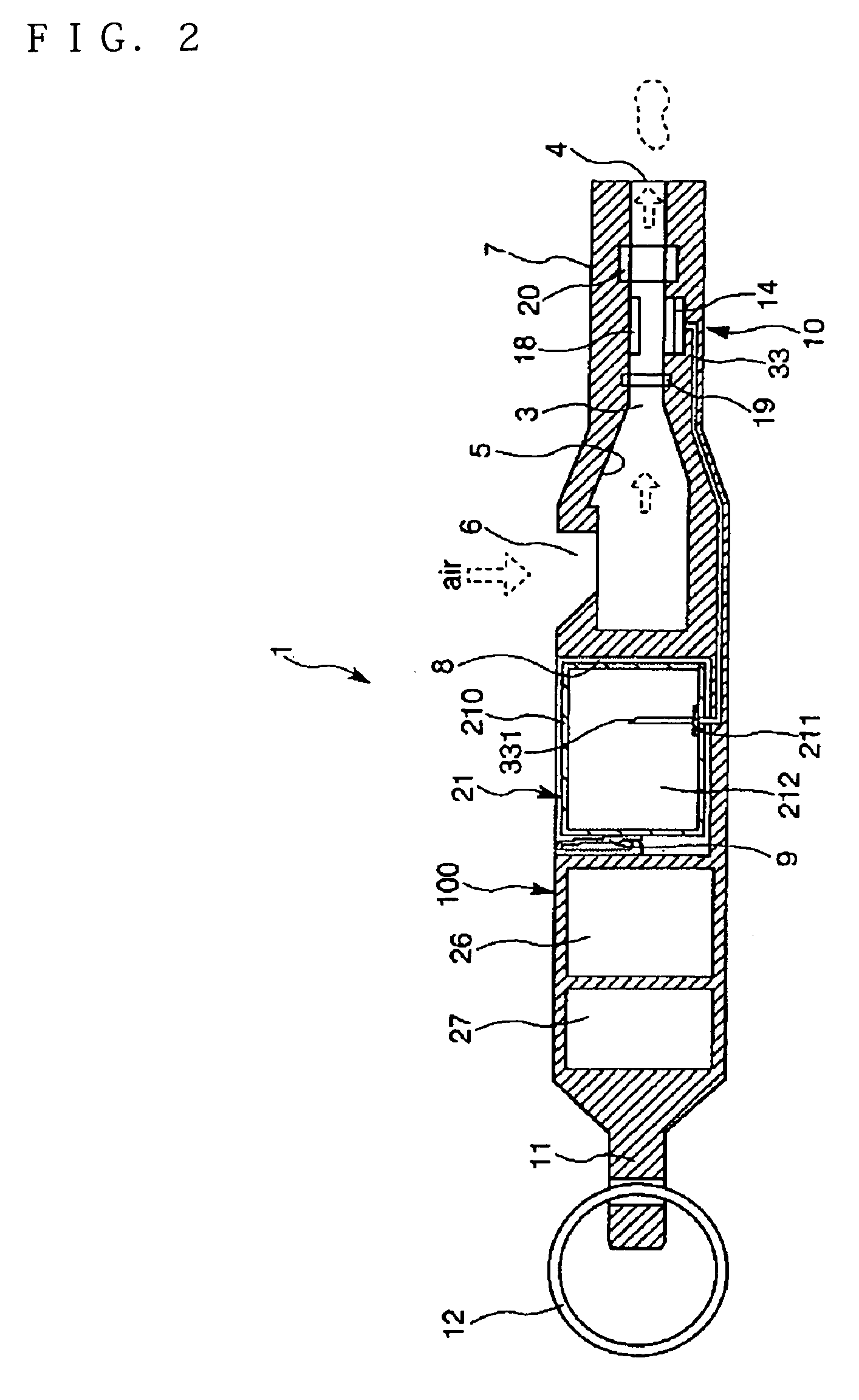
[0043]In FIGS. 1 to 5, the first embodiment in the case where an atomizing device of the invention is applied to the electronic inhalator apparatus is shown. FIG. 1 is a plan view showing the entire of the electronic inhalator apparatus, FIG. 2 is a sectional view of FIG. 1, FIG. 3 schematically shows a constitution example of discharge means and atomizing means in FIG. 2, FIG. 4 is a sectional view showing the constitution example of the discharge means, and FIG. 5 is a block diagram of the electronic inhalator apparatus.

[0044]Note that, for convenience of explanation, the left side in FIGS. 1 and 2 is referred to as a “leading end” and the right side is referred to as a “base end” in the description.

[0045]As shown in FIGS. 1 and 2, an electronic inhalator apparatus 1 includes an apparatus main body 100 having an overall form of rod (whistle) shape and a cartridge 21 having a storage part in which a liquid matter including a predetermined component taken in by a living body (herein...

second embodiment

[0108]Next, the second embodiment will be described.

[0109]FIG. 6 schematically shows an example of discharge means and atomizing means in the second embodiment of the atomizing device of the invention.

[0110]As described below, the atomizing device 10 of the second embodiment will be described with a focus on the point different from the above described first embodiment, and the description of the same parts will be omitted.

[0111]In the atomizing device 10 of the second embodiment, the atomizing means 18 is constituted by vibrating means for receiving and vibrating the droplets of the liquid matter discharged from the nozzles 16 of the respective discharge heads 15 to atomize them.

[0112]That is, as shown in FIG. 6, the atomizing means 18 has a droplet receiving plate (droplet receiving part) 181 for receiving the droplets of the liquid matter discharged from the nozzles 16 of the respective discharge heads 15 and a vibrating part 183 provided below the droplet receiving plate 181 in ...


PUM


Abstract

An atomizing device is provided that comprises: a casing having a release opening; discharging means provided within the casing and having at least one discharge head for discharging a liquid matter as droplets from a nozzle communicating with a cavity by driving an actuator to change a pressure within the cavity filled with the liquid matter; and atomizing means provided within the casing for atomizing the droplets discharged from the discharging means. It is preferred that at least a part of the discharging means and / or at least a part of the atomizing means are detachably mounted to the casing.

Description

RELATED APPLICATIONS[0001]This application claims priority to Japanese Patent Application No. 2003-291632 filed Aug. 11, 2003 which is hereby expressly incorporated by reference herein in its entirety.BACKGROUND[0002]1. Technical Field[0003]The present invention relates to an atomizing device.[0004]2. Background Art[0005]One known type of inhalator apparatus for inhaling flavors, medical agents, etc., is a neburizer inhalator equipped with an atomizing device (for example, see Publication of Japanese Patent Application No. 2001-149473).[0006]However, by various types of conventional atomizing devices, the released amount (inhaled amount) of a released matter such as a flavor or a medical agent can not be controlled accurately. Accordingly, the range of application is restricted.[0007]A purpose of the invention is to provide an atomizing device capable of atomizing a liquid matter and controlling the released amount of the atomized liquid matter (released matter) easily and accuratel...

Claims


Application Information

Patent Timeline
Patent Type & Authority Patents(United States)
IPC IPC(8): B05B1/08A61M11/00A61M11/06A61M11/08A61M15/00A24F40/10A24F40/42A24F40/48A24F42/20A24F42/60A61M15/02B05B9/04B05B17/06
CPCA61M15/02B05B17/0607A61M15/025A61M15/06A61M16/0066A61M2016/0039A61M2205/3653A61M11/042A24F40/10A24F40/48A24F42/20A24F42/60A24F40/42
Inventor KATASE, MAKOTO
Owner SEIKO EPSON CORP
Why Eureka
Try Eureka