Eureka AIR delivers breakthrough ideas for toughest innovation challenges, trusted by R&D personnel around the world.

Acoustical switch for a directional microphone

Inactive Publication Date: 2006-11-14
KNOWLES ELECTRONICS INC
View PDF19 Cites 15 Cited by
  • Summary
  • Abstract
  • Description
  • Claims
  • Application Information

AI Technical Summary

Benefits of technology

[0007]An acoustical switch is provided for a directional microphone of a hearing aid device. The hearing aid device includes a faceplate having a switch aperture, a front port, and a rear port. The microphone includes a front inlet in communication with the front port within the face plate and a front chamber of the microphone. The microphone further includes two rear inlets in communication with the rear port within the faceplate and a rear chamber of the microphone. The acoustical switch comprises a switch actuator having a body portion and a lever portion. The body portion includes a first closure surface and a second closure surface. The switch actuator is adapted to be disposed within the sw

Problems solved by technology

Present hearing aid microphones are typically limited to being optimized for directional sensitivity or omnidirectional sensitivity to sounds that impinge upon the diaphragm of the microphone.
However, undesirable noise may occur within the hearing aid when a microphone that is optimized for a given directional component of an impinging sound receives higher levels of sound having other directional components.
When a hearing aid user is trying to carry on a conversation within a crowded room, an omnidirectional hearing aid system does not allow the user to easily differentiate between the voice of the person the user is talking to and background or crowd noise.
This change in sensitivity can be very uncomfortable to the hearing aid user.

Method used


Image

  • Acoustical switch for a directional microphone
  • Acoustical switch for a directional microphone
  • Acoustical switch for a directional microphone

Examples


Embodiment Construction

[0024]While the present invention will be described fully hereinafter with reference to the accompanying drawings, in which particular embodiments are shown, it is to be understood at the outset that persons skilled in the art may modify the invention herein described while still achieving the desired result of this invention. Accordingly, the description which follows is to be understood as a broad informative disclosure directed to persons skilled in the appropriate arts and not as limitations of the present invention.

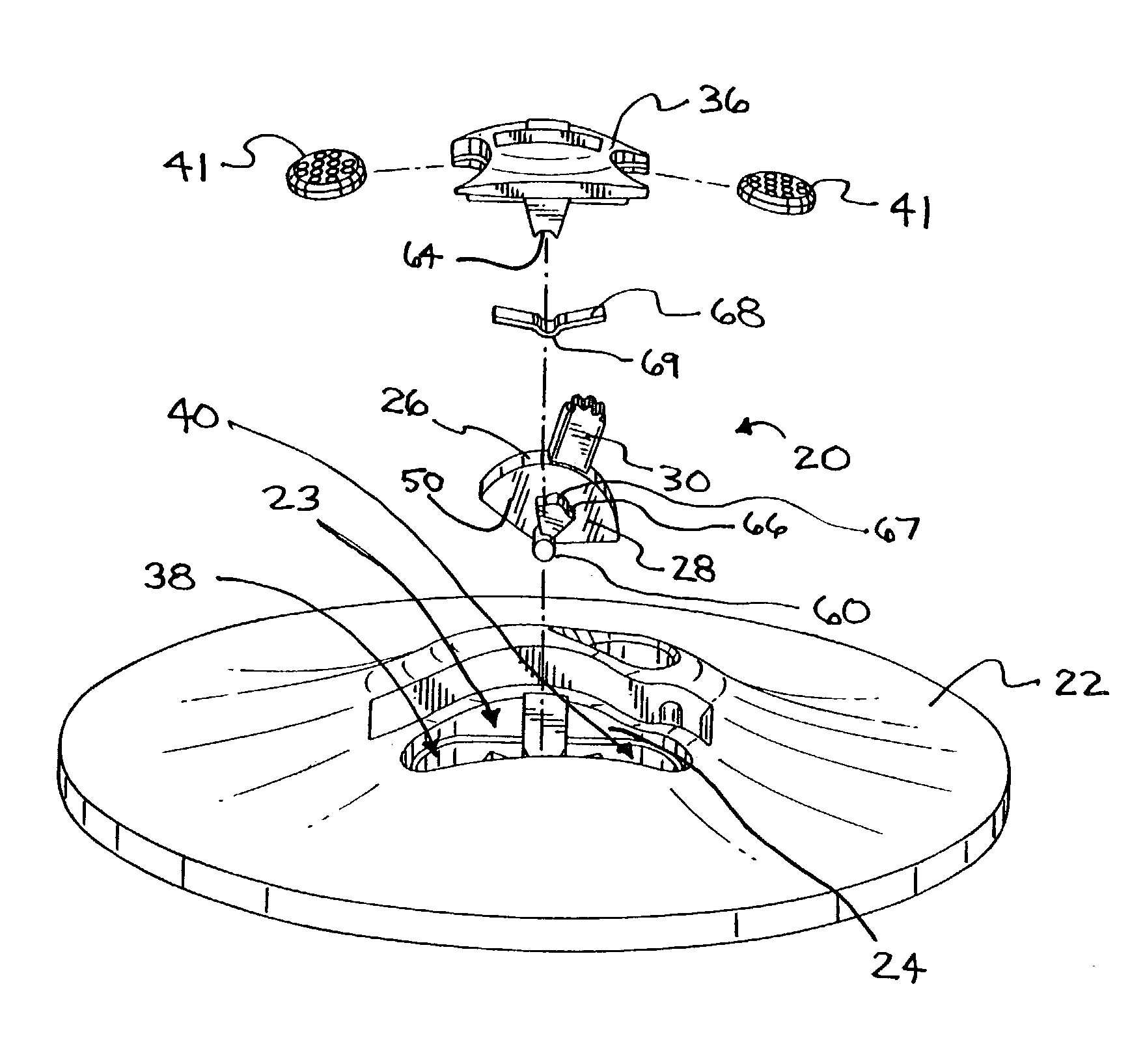
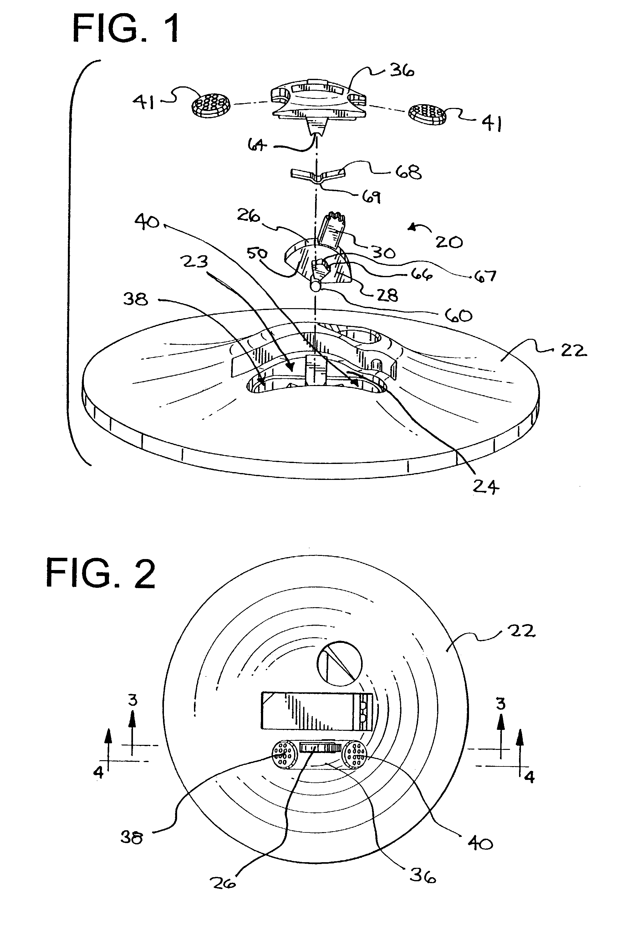
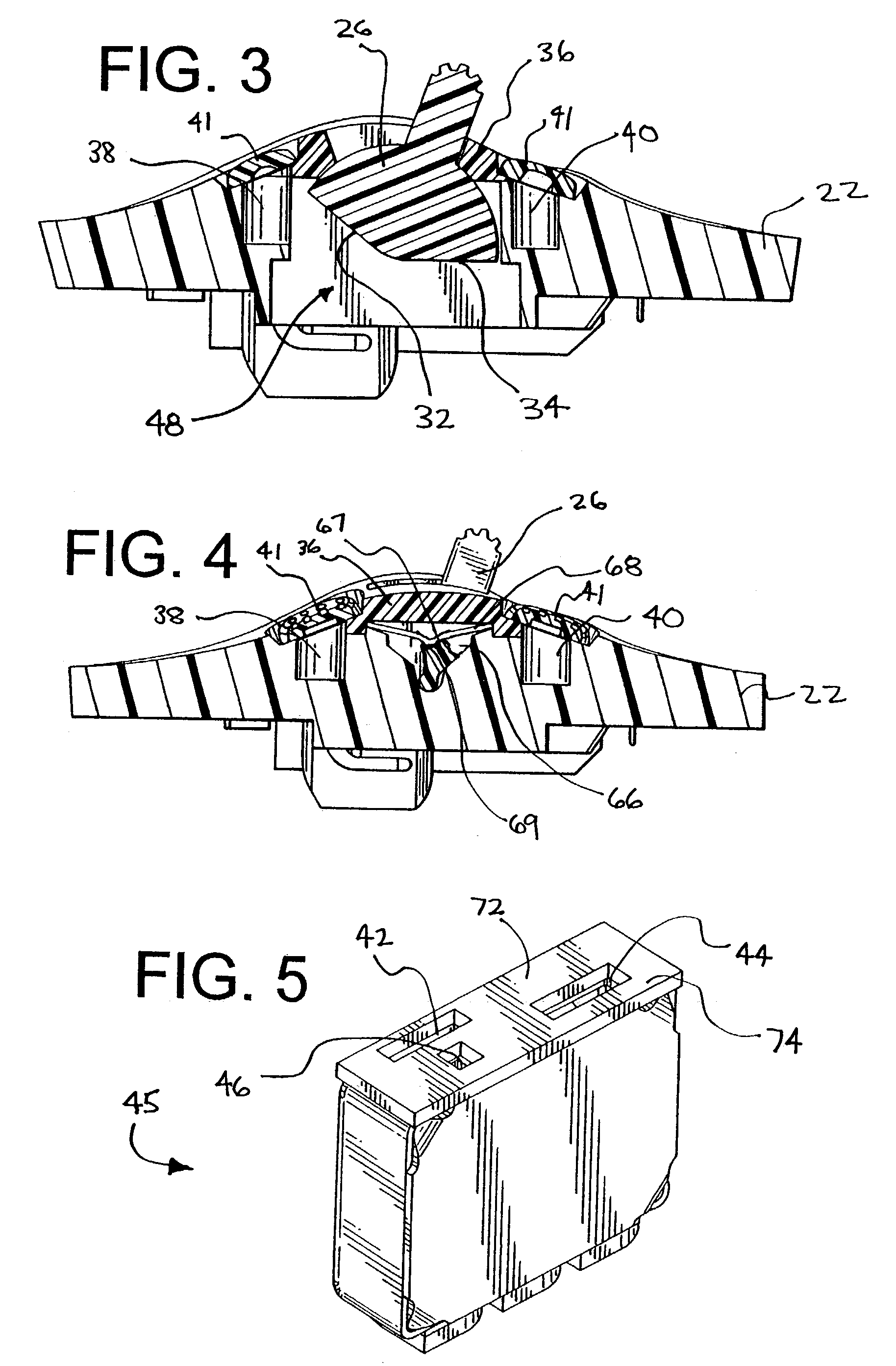
[0025]An embodiment in accordance with the present invention is shown in FIGS. 1–5 as an acoustical switch 20 for use within a faceplate 22 of a hearing aid device (not shown). The faceplate includes a switch aperture 23 that defines a side surface 24 of the aperture 23. The switch 20 includes a switch actuator 26 having a body portion 28 and a lever portion 30. The body portion 28 includes a first closure surface 32 and a second closure surface 34, as shown in FIG. ...


PUM


Abstract

An acoustical switch is provided for a directional microphone of a hearing aid device. The hearing aid device includes a faceplate having a switch aperture, a front port, and a rear port. The microphone includes a front inlet in communication with the front port within the face plate and a front chamber of the microphone. The microphone further includes two rear inlets in communication with the rear port within the faceplate and a rear chamber of the microphone. The acoustical switch comprises a switch actuator having a body portion and a lever portion. The body portion includes a first closure surface and a second closure surface. The switch actuator is adapted to be disposed within the switch aperture of the face plate of the hearing aid device such that the body portion is disposed adjacent to the inlets of the microphone. The switch actuator s moveable between a first position wherein the first closure surface of the body portion is adapted to cover one of the rear inlets of the microphone, and a second position wherein the second closure surface of the body portion is adapted to cover the other of the rear inlets of the microphone. The body portion includes a side surface having an acoustical resistance associated therewith wherein the acoustical resistance is substantially greater than an acoustical resistance between either of the ports and its respective microphone chamber.

Description

RELATED APPLICATION[0001]This application claims priority to U.S. Provisional Application Ser. No. 60 / 373,119, filed Apr. 17, 2002.TECHNICAL FIELD[0002]The present invention generally relates to mechanical switches for microelectronic devices, and more particularly to an acoustical switch for a directional microphone in a hearing aid.BACKGROUND OF THE INVENTION[0003]Present hearing aid microphones are typically limited to being optimized for directional sensitivity or omnidirectional sensitivity to sounds that impinge upon the diaphragm of the microphone. The directivity of a microphone is the sensitivity of a microphone to a sound component at different angles of incidence. The microphone is typically optimized to be more sensitive to one component of the sound over the other. However, undesirable noise may occur within the hearing aid when a microphone that is optimized for a given directional component of an impinging sound receives higher levels of sound having other directional...

Claims


Application Information

Patent Timeline
IPC IPC(8): H04R25/00
CPCH04R25/00H04R25/402H04R2225/61H04R25/603
Inventor MCSWIGGEN, JOHN P.
Owner KNOWLES ELECTRONICS INC
Why Eureka
Eureka Blog
Learn More