Composite beam

a composite beam and beam technology, applied in the field of composite beams, can solve the problems of difficult to obtain good quality seasoned wood free of warping, prior proposals for composite beams have failed to appear, and the material suitable for making such beams and trusses is simply not available, so as to achieve less expensive and more readability

Inactive Publication Date: 2006-11-28
STEADMAN WILLIAM
View PDF34 Cites 15 Cited by
  • Summary
  • Abstract
  • Description
  • Claims
  • Application Information

AI Technical Summary

Problems solved by technology

In many parts of the world timber suitable for making such beams and trusses is simply not available.
In those parts of the world where timber is plentiful, it is often difficult to obtain good quality seasoned wood free of warping.
While it is esthetically desirable for a composite beam or truss to appear to be all wood, prior proposals for composites have failed to so appear, at least in beams and trusses that can be made economically.
Moreover prior proposals have typically been lacking in terms of strength per unit of weight.

Method used


Image

  • Composite beam
  • Composite beam
  • Composite beam

Examples


Embodiment Construction

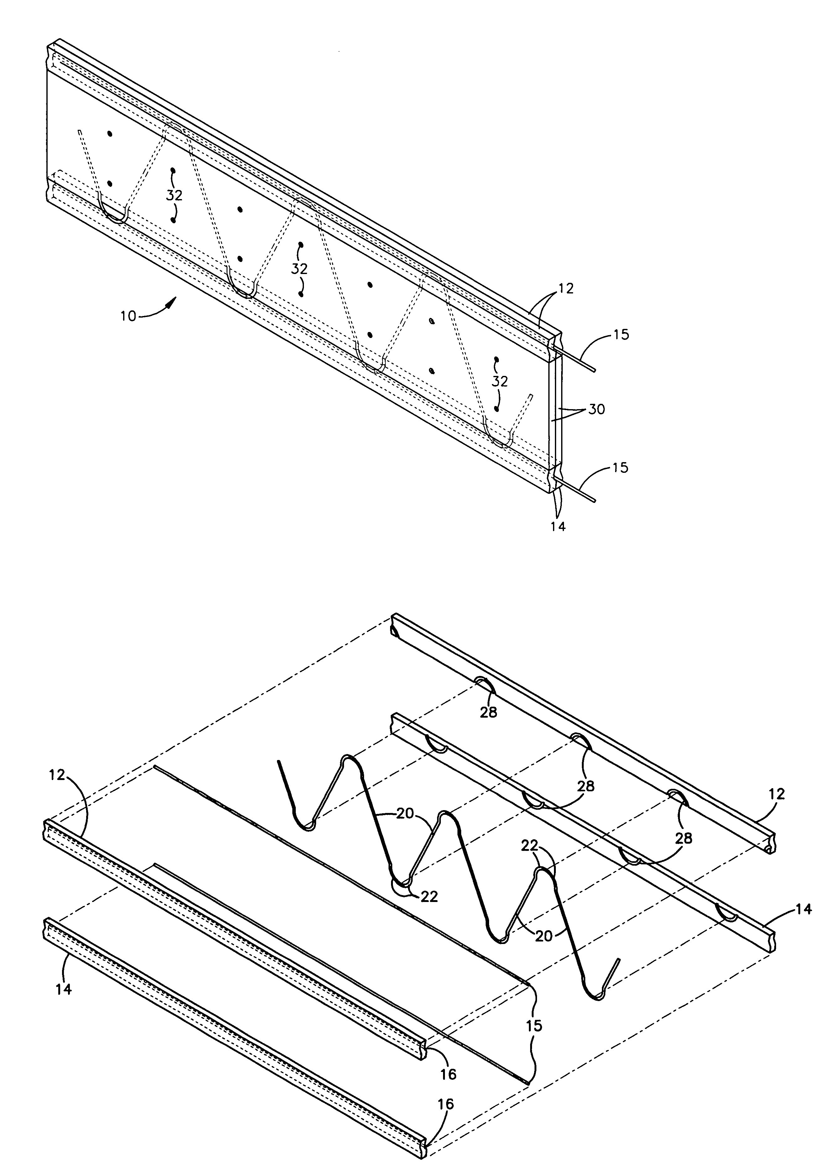
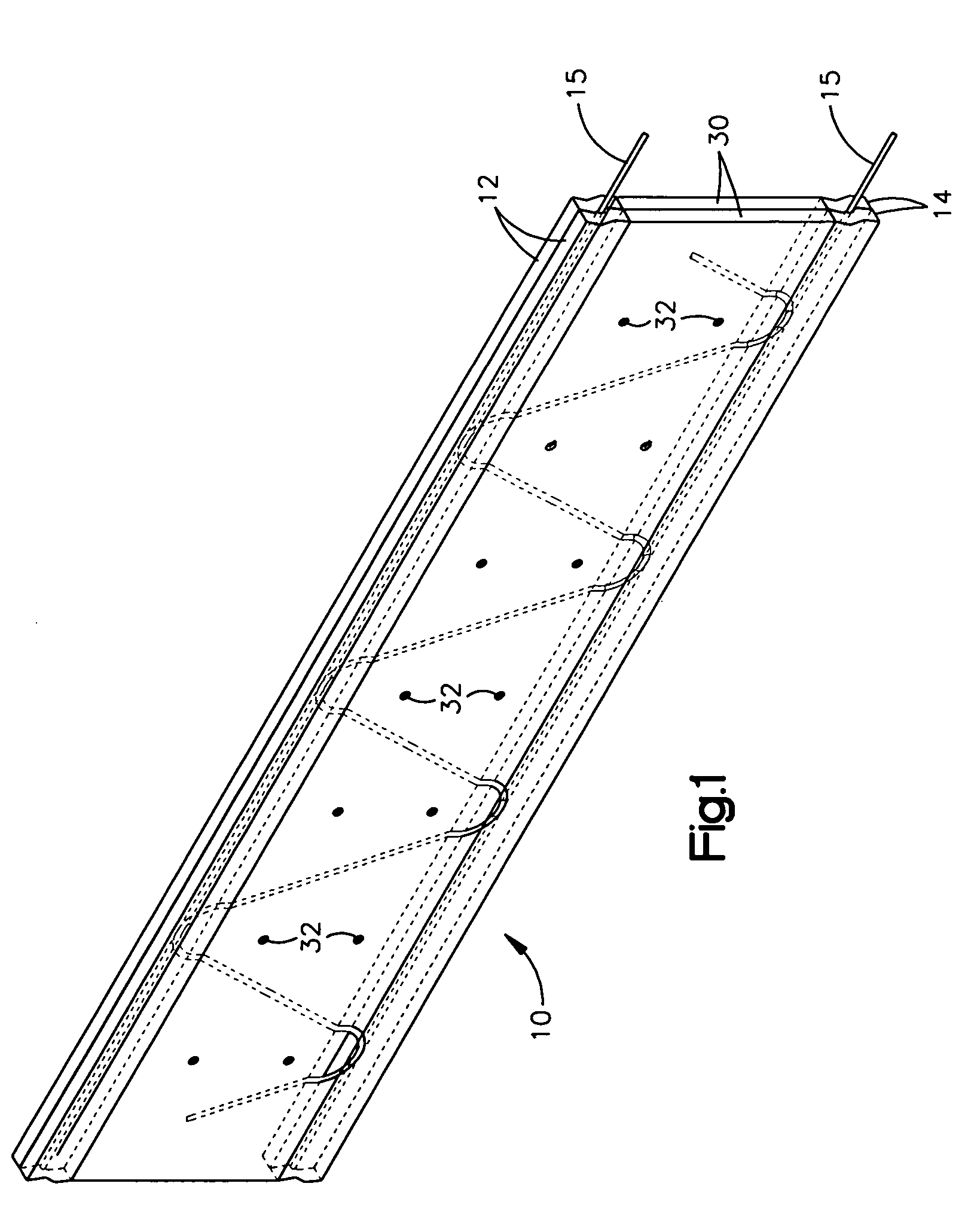
[0017]Referring now to the drawings and to FIG. 1 in particular a composite beam made in accordance with the present invention is shown generally at 10. The beam includes upper and lower pairs of elongate wood members 12,14.

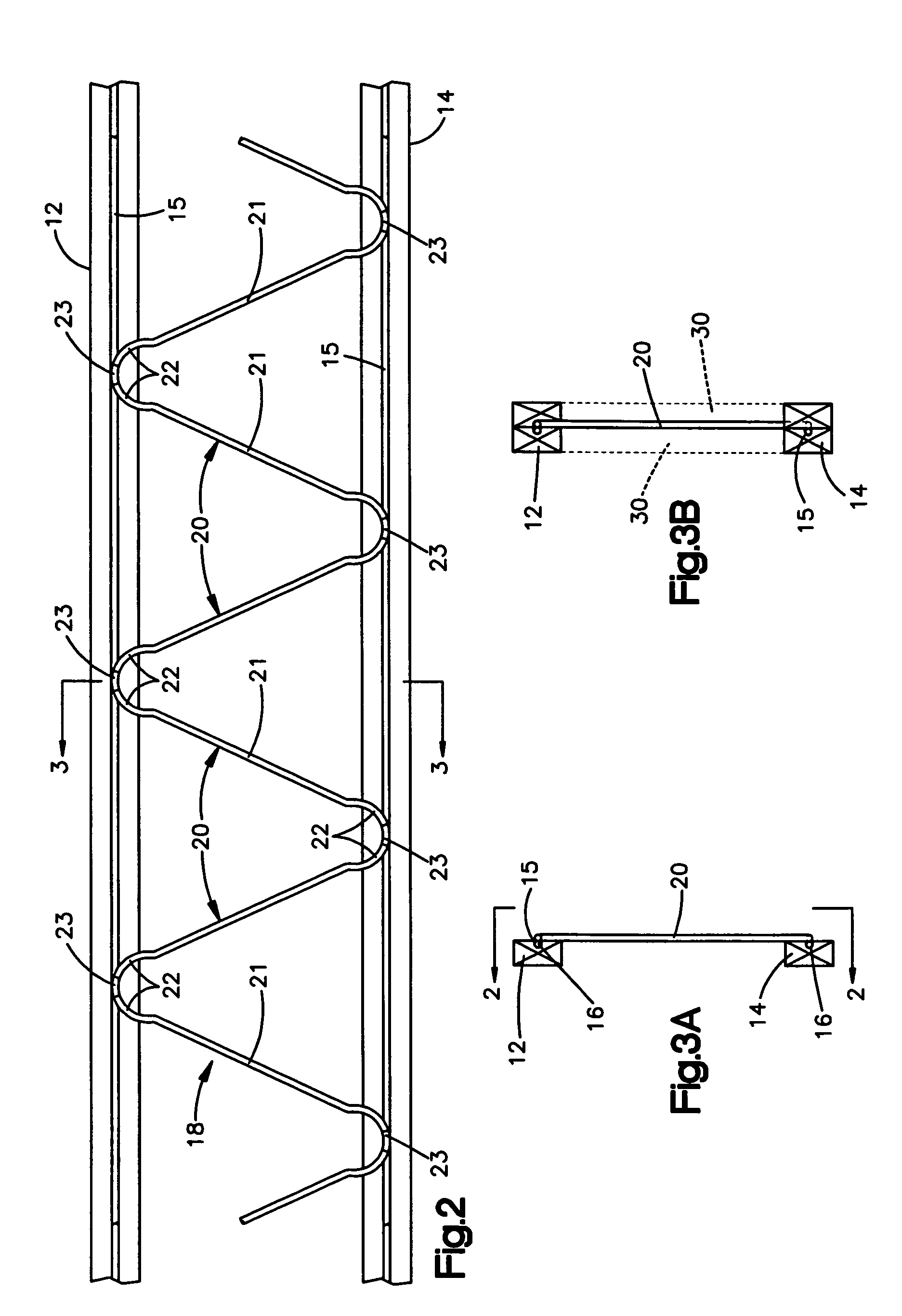
[0018]A steel reinforcement is provided. The reenforcement includes upper and lower, elongate, straight rods 15. One of each elongate member pair 12,14 includes an elongated groove 16 shaped to receive and house an associated one of the rods 15. The reenforcement also includes a sinuous assembly 18. The sinuous assembly is composed of serpentine rods or sections 20 each consisting of a straight central part 21 and spaced arcuately curved end parts or spacer portions 22.

[0019]The sections 20 are alternately oppositely oriented with the end parts 22 abutting to define arcuately curved junctures. The spaced arcuately curved end parts 22 define a space or gap 23 between the end parts 22 at the arcuately curved junctures. Each abutting pair of end parts 22 is welded t...


PUM


Abstract

A composite beam is disclosed. The component has spaced pairs of elongate wood members, the members of each pair being in face to face mating orientation. A generally sinuous shaped spacer rod sub assembly having spacer portions connected at junctures is provided. The elongate member pairs each having mating faces including recesses contoured to receive one of the junctures and parts of connected spacer portions. The connected spacer portions each project angularly in opposed directions from their associated juncture and its recess in one of the pairs toward the other pair of members. Each of the junctures is disposed in an associated recess in the members whereby to provide a composite beam having the pairs of elongate members maintained in spaced relationship by the rod subassembly.

Description

[0001]The present invention relates to building components and more particularly to a composite beams of steel reinforced wood.BACKGROUND[0002]Joists and trusses in frame buildings historically have been made from solid wood beams. Depending on the size of a building and anticipated loads to be supported, such beams are nominally two inches thick and six, eight or ten inches or more in width.[0003]In many parts of the world timber suitable for making such beams and trusses is simply not available. In those parts of the world where timber is plentiful, it is often difficult to obtain good quality seasoned wood free of warping.[0004]There have been proposals for composites to serve as beams and trusses. Such composites are more resistant to warping than solid wood beams. In addition such composites if properly designed and construct have greater strength per unit of weight at least as compared with the wood varieties used in construction.[0005]While it is esthetically desirable for a ...

Claims


Application Information

Patent Timeline
Patent Type & Authority Patents(United States)
IPC IPC(8): E04C3/02
CPCE04C3/08E04C3/292
Inventor STEADMAN, WILLIAM
Owner STEADMAN WILLIAM
Why Eureka
Try Eureka