Fuel cell and separator therefor

a fuel cell and separator technology, applied in the field of polymer electrolyte fuel cells, can solve the problems of inability to function as a buffer, damage such as fractures and breaks in the drawn portion, etc., and achieve the effect of improving power generation characteristics and reducing the internal resistance of the cell

Inactive Publication Date: 2006-12-12
HONDA MOTOR CO LTD
View PDF3 Cites 4 Cited by
  • Summary
  • Abstract
  • Description
  • Claims
  • Application Information

AI Technical Summary

Benefits of technology

[0007]Therefore, an object of the present invention is to provide a fuel cell and a separator therefor, in which the surface pressure of the protrusions can be as uniform as possible, and the internal resistance of the cell can be reduced, so that the power generation characteristics can be improved.
[0009]According to the invention, when plural fuel cells are layered to form a fuel cell stack, the protrusions of the separator are press contacted with the electrode of the membrane electrode assembly. In this condition, the spacer portion is bent at two drawn portions as an inflection point following the assembling pressure. As a result, the spacer portion functions as a buffer like a plate spring, and the surface pressure in the protrusion with respect to the electrode is dispersed to be uniform. That is, in the portion in which the surface pressure is large, the bending angle of the spacer portion is large. In contrast, the portion, in which the surface pressure is large, is gently bent. Therefore, the surface pressure in the protrusions press contacted with the electrode is finally uniform. As a result, the contact resistance between the electrode plate and the separator is reduced, and the internal resistance of the cell is reduced and the power generating efficiency is improved.

Problems solved by technology

When the drawing ratio is less than 0.5, the drawn portion is too thin and the strength thereof is insufficient, so that damage such as fractures and breaks in the drawn portion occur.
In contrast, when the drawing ratio is more than 0.95, the strength of the drawn portion is too large, so that a function as a buffer may not be obtained.

Method used


Image

  • Fuel cell and separator therefor
  • Fuel cell and separator therefor
  • Fuel cell and separator therefor

Examples


example

[0029]Next, the advantages of the invention will be proved with reference to examples of the invention.

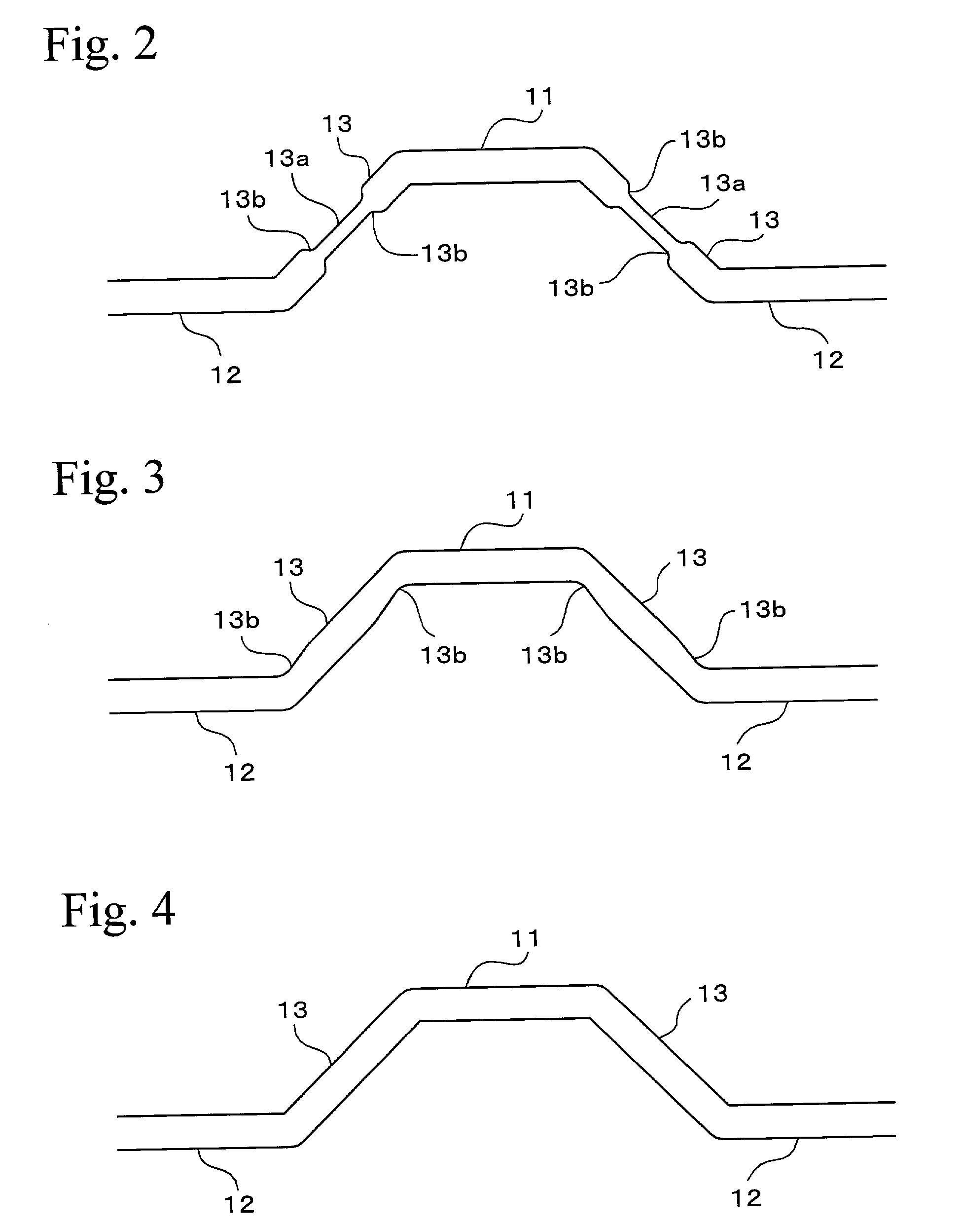
[0030]Sheets made from stainless steel (SUS 430) having thicknesses of 0.1 mm, 0.15 mm, 0.2 mm, 0.3 mm were press formed to separators (Samples Nos. 1 to 30) having the shape shown in FIG. 3 were produced. The drawing ratios in the drawn portions are shown in Table 1. The maximum thickness “a” of the protrusion, the minimum thickness “b” of the drawn portion, the depth of the gas passage, and the pitch of the gas passages are shown together in Table 1.

[0031]

TABLE 1GeneratedMaximumMinimumDepth ofPitch ofVoltage atThickness ofThickness ofGasGasDrawingCurrentProtrusionDrawn PortionPassagePassagesRatioDensity ofNo.(mm)(mm)(mm)(mm)(%)0.5 A / cm2 (V) 10.30.30.831000.66 20.30.280.8393.33330.69 30.30.260.8386.66670.71 40.30.240.83800.72 50.30.220.8373.33330.715 60.30.20.8366.66670.72 70.30.180.83600.71 80.30.150.83500.705 90.30.10.8333.33330.66100.30.050.8316.66670.62110.20.20.631000.608120....


PUM

PropertyMeasurementUnit
temperatureaaaaaaaaaa
thicknessaaaaaaaaaa
thicknessaaaaaaaaaa

Abstract

A fuel cell comprises an membrane electrode assembly formed by holding an electrolyte membrane between a pair of electrodes and a separator layered on both sides of the membrane electrode assembly for forming gas passages between the separator and the electrode. The separator includes protrusions formed on both surfaces thereof for contacting with the electrode, and a spacer portion disposed between the protrusions for substantially forming the gas passage. The protrusions and the spacer portions are arranged along a surface direction of the separator so as to form a corrugated plate. At least two drawn portions in which thickness of the spacer portion changes to a thin portion are formed between the protrusions in the spacer portion.

Description

BACKGROUND OF THE INVENTION[0001]1. Technical Field[0002]The present invention relates to polymer electrolyte fuel cells, and relates to separators for forming gas passages in fuel cells.[0003]2. Background Art[0004]In polymer electrolyte fuel cells, a separator is layered on both sides of a plate-shaped membrane electrode assembly to form a unit of a layered structure, and plural units are layered to form a fuel cell stack. The membrane electrode assembly is a three-layered structure, in which a polymerized electrolyte membrane made from a resin such as ion-exchange resin is held by a pair of gas diffusion electrode plates (positive electrode plate and negative electrode plate). The separator is formed with gas passages for flowing a gas between the gas diffusion electrode plate and the separator. According to the fuel cell, hydrogen gas as a fuel is provided to the gas passages facing the gas diffusion electrode plate at the negative electrode side, and an oxidizing gas such as ox...

Claims


Application Information

Patent Timeline
Patent Type & Authority Patents(United States)
IPC IPC(8): H01M8/02H01M8/10
CPCH01M8/0206H01M8/0254H01M8/026Y02E60/50
Inventor OHTANI, TERUYUKITSUJI, MAKOTOUTSUNOMIYA, MASAO
Owner HONDA MOTOR CO LTD
Why Eureka
Try Eureka