Disk drive head touchdown detection with improved discrimination

a technology of head touchdown and discrimination, applied in the field of head touchdown detection, can solve the problems of time-consuming approach, subject to channel setting, new channel features and significant firmware changes, etc., and achieve the effect of less sensitive to vibration and small vibration rejection

Inactive Publication Date: 2007-01-02
MAXTOR
View PDF9 Cites 71 Cited by
  • Summary
  • Abstract
  • Description
  • Claims
  • Application Information

AI Technical Summary

Benefits of technology

This patent describes two different functions performed by a servo system in a computer hard disk drive (HDD). One function tracks the position of the HDD's head while it reads or writes data on the disks. Another function detects when the head makes contact with the surface of the disk. The new feature is that this second function reduces sensitivity to vibrations more compared to the first function, which ensures smoother operation of the HDD during both read/write activities and head touchdown detection.

Problems solved by technology

The technical problem addressed in this patent text relates to finding ways for reliable, accurate, and quick detection of head touchdown in disk drives. This issue has been challenging due to current methods being time-consuming, requiring significant amounts of data collection, and potentially causing damage to the heads if they fail to detect it properly.

Method used


Image

  • Disk drive head touchdown detection with improved discrimination
  • Disk drive head touchdown detection with improved discrimination
  • Disk drive head touchdown detection with improved discrimination

Examples


Embodiment Construction

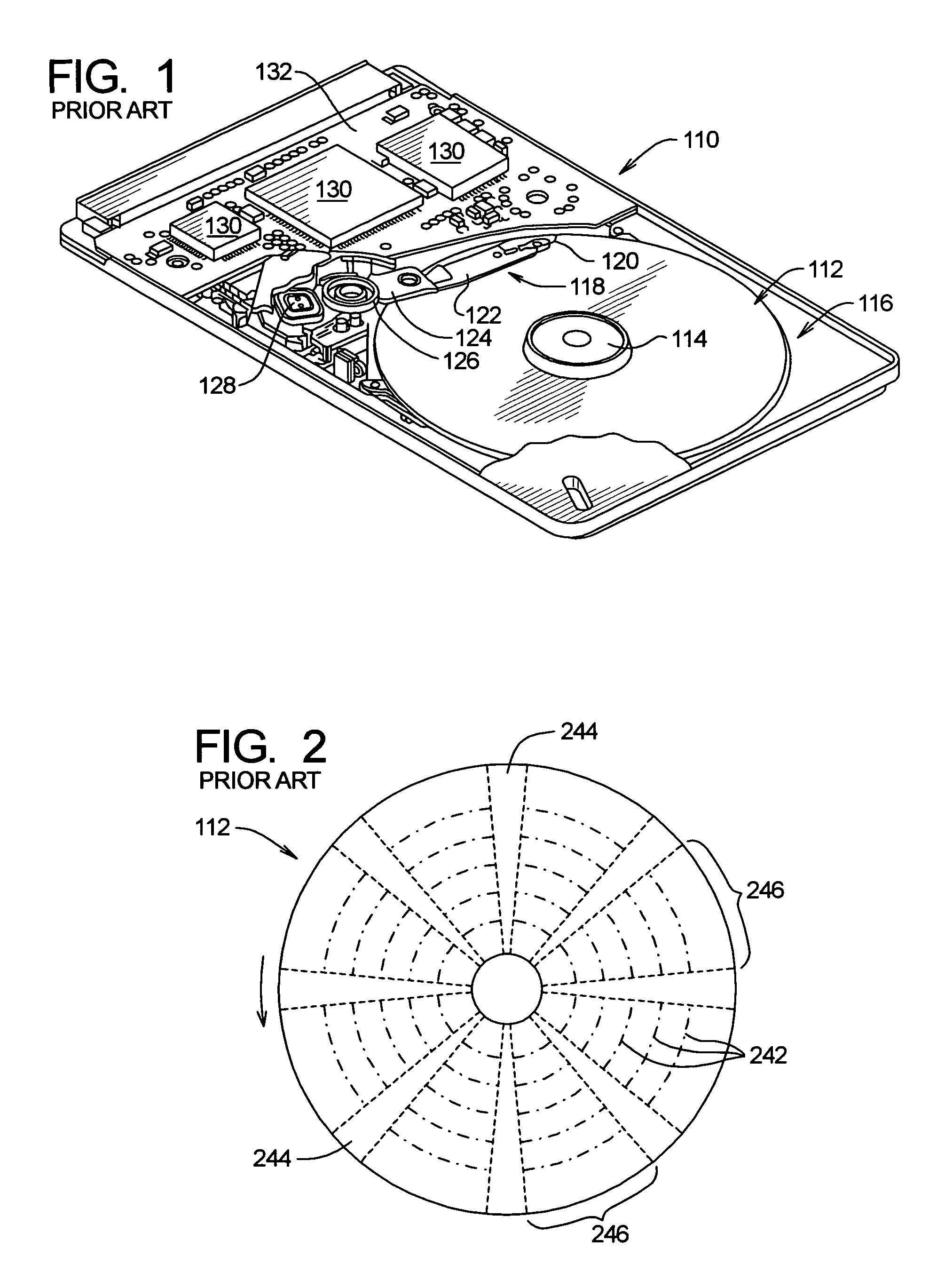
[0027]FIG. 1 illustrates a conventional disk drive 110 that includes a magnetic storage disk 112 that is rotated by a spindle motor 114. The spindle motor 114 is mounted on a base plate 116. An actuator arm assembly 118 is also mounted on the base plate 116.

[0028]The actuator arm assembly 118 includes a read / write head 120 mounted on a flexure arm 122 which is attached to an actuator arm 124 that rotates about a bearing assembly 126. The actuator arm assembly 118 also contains a voice coil motor 128 which moves the head 120 relative to the disk 112. The spindle motor 114, the head 120 and the voice coil motor 128 are coupled to electronic circuits 130 mounted on a printed circuit board 132. The electronic circuits 130 include a read channel, a microprocessor-based controller and a random access memory (RAM).

[0029]The disk drive 110 typically includes multiple disks 112 and therefore multiple actuator arm assemblies 118. However, the disk drive 110 can include a single disk 112 and a...


PUM


Abstract

A disk drive detects head touchdown based on a magnitude of a position error signal at a discrete frequency. The discrete frequency is one-half the disk rotation frequency or an integral multiple of the disk rotation frequency. The head is heated by turning on a heater at the discrete frequency, thereby injecting bias into a servo system that increases the PES magnitude. In addition, the servo system has a first transfer function for tracking the head during read and write operations and a second transfer function for tracking the head during head touchdown detection. The second transfer function has smaller vibration rejection than the first transfer function so that the disk drive is less sensitive to vibration during read and write operations than during head touchdown detection.

Description


Claims


Application Information

Patent Timeline
Owner MAXTOR
Why Eureka
Try Eureka