Piston-activated valve and methods and apparatus for restraining free play in a device

a technology of activated valves and pistons, applied in the field of mechanical fittings and tolerability, can solve the problems of physical largeness and heavyness of pistons, limited peak pressure, and inability to increase pressure in the first potential method, and achieve the effect of preventing free play

Inactive Publication Date: 2006-05-16
SCOT
View PDF19 Cites 4 Cited by
  • Summary
  • Abstract
  • Description
  • Claims
  • Application Information

AI Technical Summary

Benefits of technology

[0013]These and other objects are met by the present invention. In one embodiment, the present invention provides a method and apparatus for preventing free play in a device, such as a pyrotechnic valve device. An apparatus of this embodiment includes an eccentric sleeve, that is, a sleeve with a cylindrical outer surface and a bore which is not coaxial with the outer surface. Rotation of the eccentric sleeve adjusts the position of the bore in the eccentric sleeve, which is mated with a pin, such as a shear pin.

Problems solved by technology

Further, peak pressures are limited by the ability of O-rings and other gas-tight fittings to contain such pressures.
However, such pressure increase in this first potential method can be unacceptable because of a need for initiation redundancy in the device.
A second potential method of addressing the above desired needs in a pyrotechnic valve is to increase the piston area, which can be undesirable for two reasons.
First, increasing the piston area can make the piston physically large and heavy.
Second, more propellant charge or possibly even an additional booster charge would be required in the initiators.
These characteristics can be undesirable from a design standpoint and can generally raise the cost of the pyrotechnic valve device.
Pyrotechnic valve devices, such as those used in rocketry, for example, are often subject to considerable vibration.
If there is “play” between the parts, vibrational damage can result.

Method used


Image

  • Piston-activated valve and methods and apparatus for restraining free play in a device
  • Piston-activated valve and methods and apparatus for restraining free play in a device
  • Piston-activated valve and methods and apparatus for restraining free play in a device

Examples


Embodiment Construction

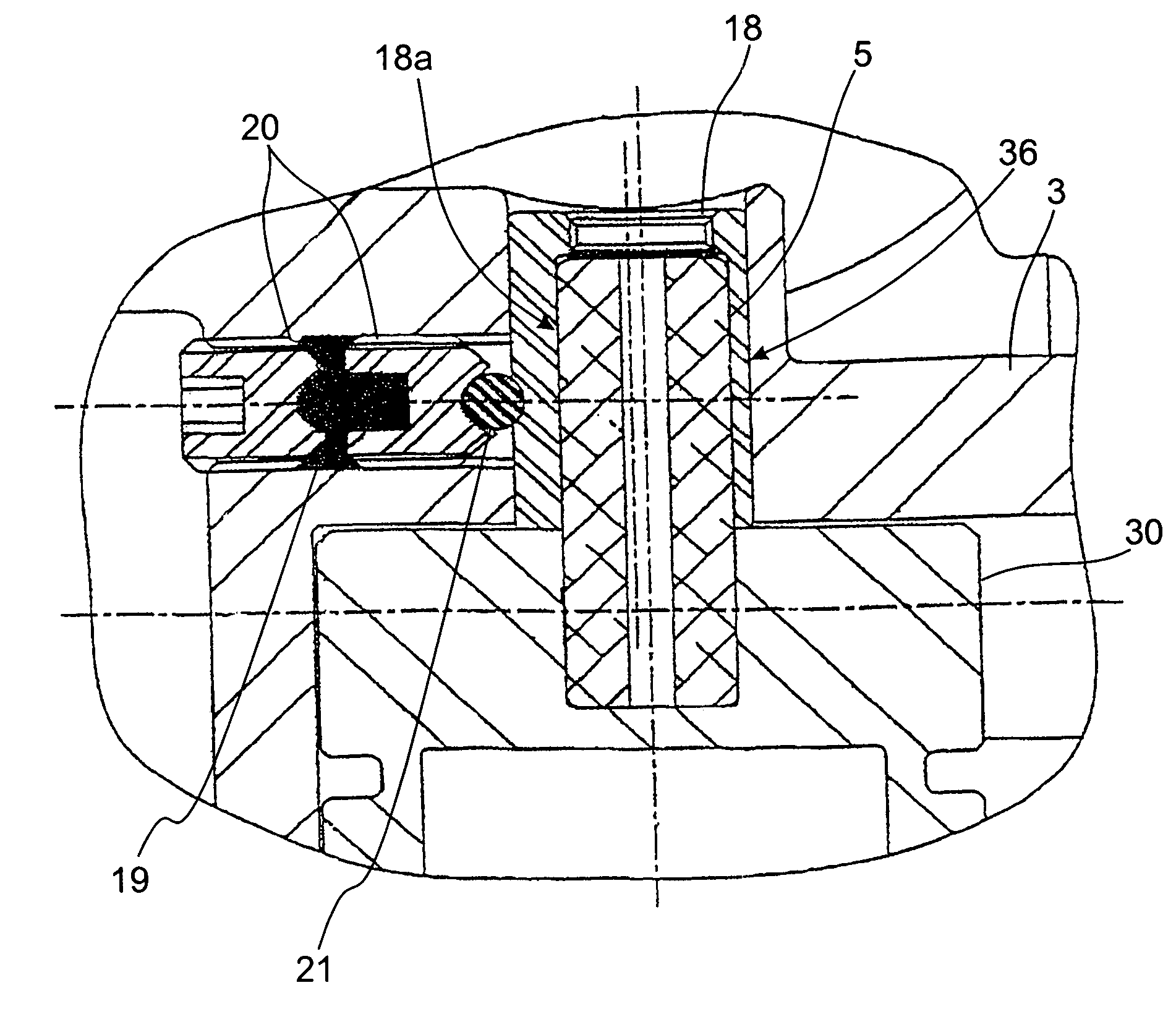
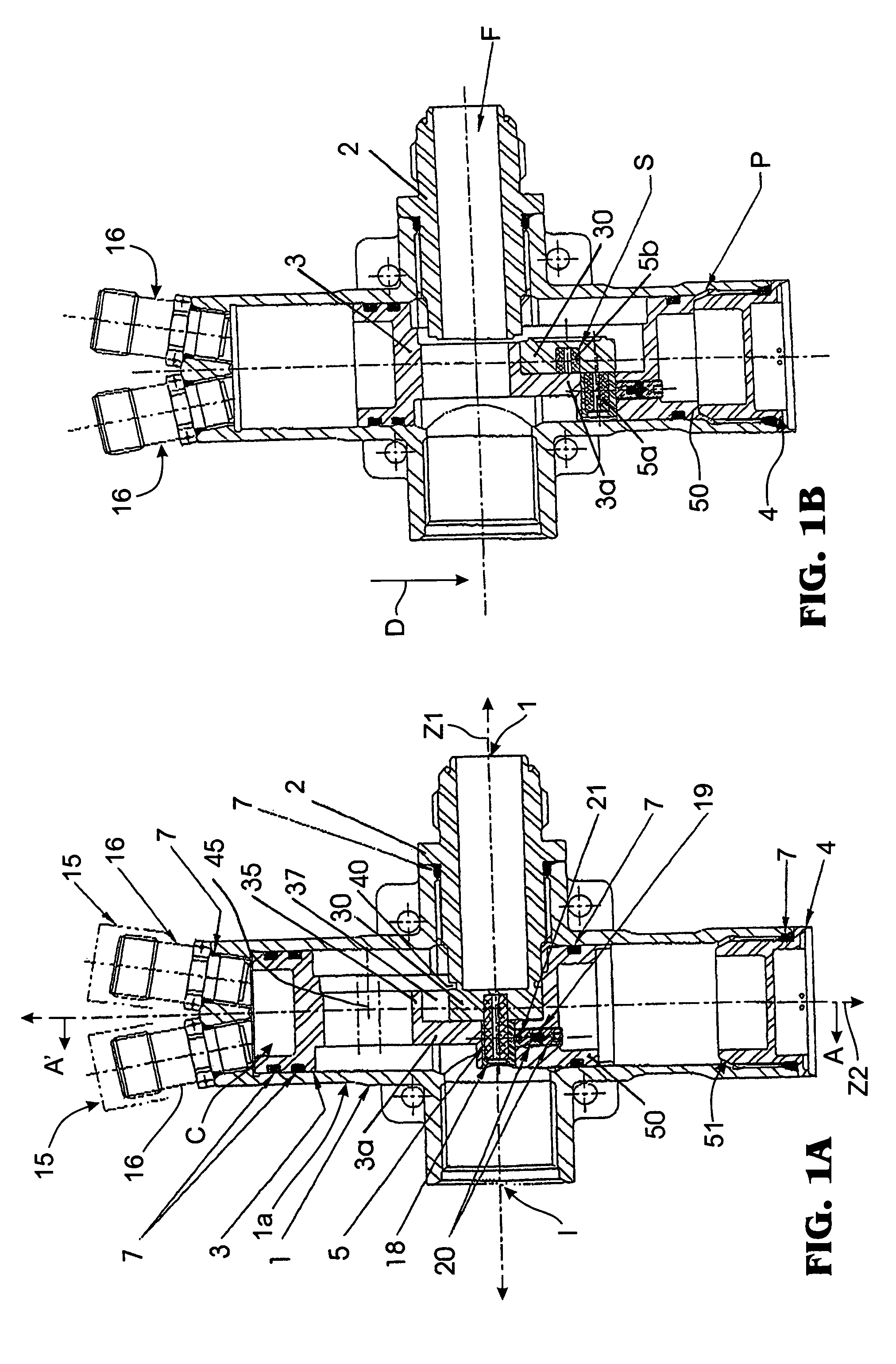
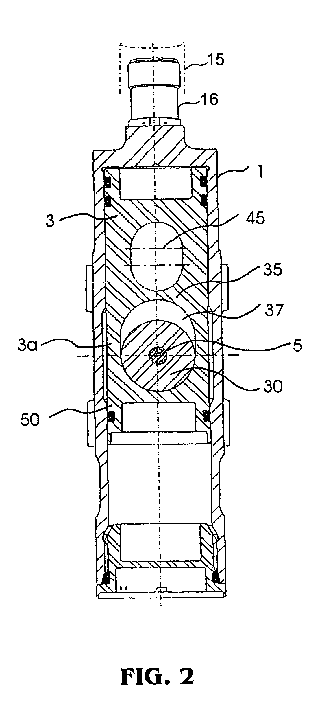
[0027]An embodiment of a valve device of the present invention is a pyrovalve, that is, a pyrotechnically activated valve. Pyrovalves can be used, for example, in rockets for valves which are activated only once. For example, a pyrovalve can be a normally closed valve mounted in proximity to a main rocket motor. The valve can be installed in a flow path between a pressurized helium tank and the interior of the main motor, for example. During the first phase of flight, the main motor burns to provide propulsion. During this time, the valve remains in the normally closed position, preventing the flow of helium to the motor. When the main rocket motor burns out, the valve is actuated to provide a helium purge to the motor. This brings the motor rapidly to a zero thrust permitting stage separation shortly thereafter.

[0028]An embodiment of a valve device of the present invention as a pyrovalve is shown in FIGS. 1A, 1B, 2, 5, 6A–6F, 7A–7C and 8A–8I, with FIG. 1A illustrating the pyrovalve...


PUM

PropertyMeasurementUnit
pressureaaaaaaaaaa
pressureaaaaaaaaaa
movementaaaaaaaaaa

Abstract

Apparatus and methods for fitting mechanical parts to minimize prevent free play are described. An apparatus having a piston is designed so as to restrain the piston before actuation, and so as to allow the piston to gain momentum before striking an object. The described apparatus are applicable to devices involving shearable elements. An embodiment of the invention relates to a pyrotechnically activated valve incorporating such features to minimize free play in conjunction with such features so as to restrain the piston and also allow the piston to gain momentum.

Description

CLAIM OF PRIORITY[0001]This application makes reference to, incorporates the same herein by reference, and claims all benefits accruing under 35 U.S.C.§119(e) from my application PISTON-ACTIVATED VALVE filed as a provisional application in the U.S. Patent and Trademark Office as U.S. application Ser. No. 60 / 261,199, filed on Jan. 16, 2001.BACKGROUND OF THE INVENTION[0002]1. Field of the Invention[0003]The present invention relates to mechanical fittings and tolerancing, in particular to fittings found in shearable devices, and more particularly to pyrotechnically activated devices such as valves.[0004]2. Background of the Invention[0005]Pyrotechnic valves are commonly used in rockets for valves which must be opened reliably one time. Typically, these valves contain a seal tube which holds a pressurized gas, and this seal tube is pyrotechnically sheared to open the sealed end of the seal and start the flow of gas. The seal tube typically needs to be very strong in order to support th...

Claims


Application Information

Patent Timeline
Patent Type & Authority Patents(United States)
IPC IPC(8): F16K17/40F02K9/54F02K9/92
CPCF02K9/54F02K9/92F16B2200/10F16K13/06Y10T83/8863Y10T137/1647Y10T137/1669
Inventor EVANS, GRIFFITH S.
Owner SCOT
Why Eureka
Try Eureka