
Remote sensing device

Active Publication Date: 2020-09-15
APPLE INC
View PDF20 Cites 16 Cited by
  • Summary
  • Abstract
  • Description
  • Claims
  • Application Information

AI Technical Summary

Benefits of technology

The remote sensing device described in this patent is a small and compact LiDAR module that can provide high-resolution 3D imaging without the need for a high-resolution FPA and its corresponding digital receiver chain. It also requires less power than conventional systems and is less sensitive to vibrations due to its small size. These features make it suitable for integration into tight spaces and make it easy to use. Overall, the device offers improved imaging capabilities at a lower cost and with improved reliability.

Problems solved by technology

Conventional scanning systems (e.g., LiDAR systems) are typically bulky and large in size.

Method used


Image

  • Remote sensing device
  • Remote sensing device
  • Remote sensing device

Examples


Embodiment Construction

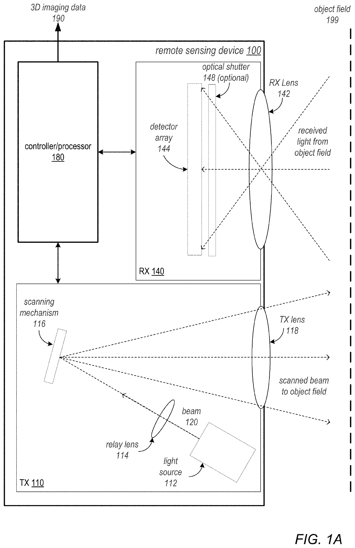
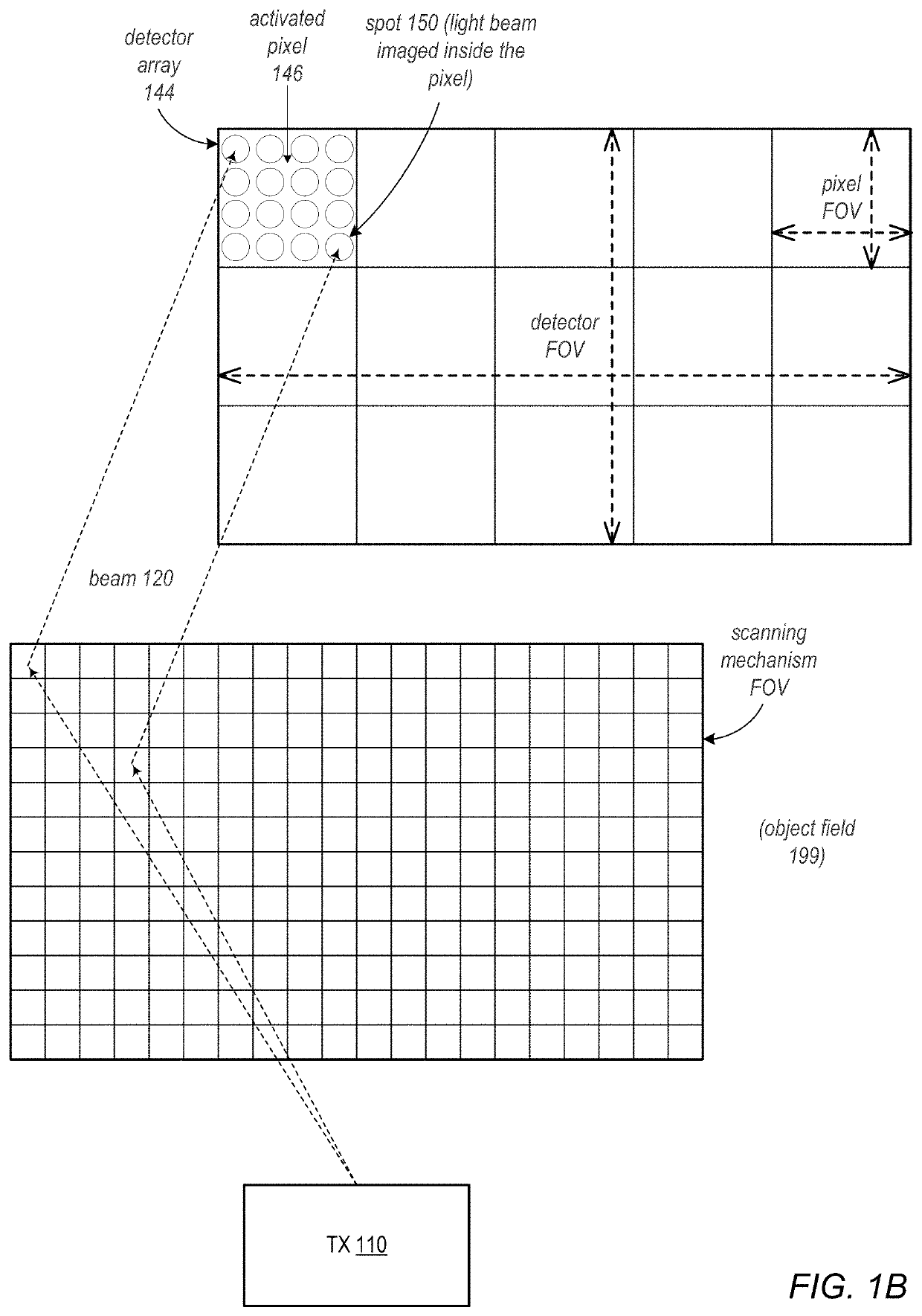
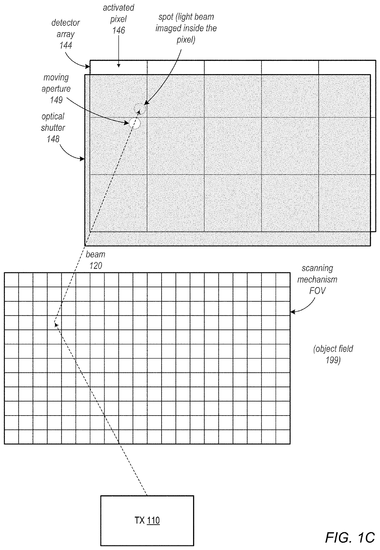
[0004]Embodiments of the present disclosure may provide a compact remote sensing device that includes a transmit component that scans a beam of light across a scene or object field, and a receive component that receives return light from the object field. The transmit component includes a small, fast scanning mechanism, for example a MEMS (microelectromechanical system) mirror or mirror array, or a piezoelectric steering mirror (referred to as a piezo mirror), that scans a beam of light emitted by a light source across a field of view (FOV). The receive component includes a focal plane array (FPA) with a FOV at least large enough to capture the FOV of the scanning mechanism. The FPA may be a low resolution FPA (i.e., with fewer pixels than the resolution of the scanning mechanism), and the light beam may be scanned and captured at multiple spots (or sub-pixels) within the pixels of the FPA. The FPA may be implemented according to avalanche photodiode (APD) technology, PIN diode tech...


PUM


Abstract

A compact remote sensing device is described that includes a transmit component that scans a beam of light across a scene or object field, and a receive component that receives return light from the object field. The transmit component includes a small, fast scanning mechanism such as a MEMS mirror or a piezo mirror that scans a beam of light emitted by a light source across a field of view (FOV). The receive component includes a focal plane array (FPA) with a FOV at least large enough to capture the FOV of the scanning mechanism. The FPA may be a low resolution FPA (i.e., with fewer pixels than the resolution of the scanning mechanism), and the light beam may be scanned and captured at multiple spots within the pixels of the FPA.

Description

[0001]This application claims benefit of priority to U.S. Provisional Application No. 62 / 377,404, filed Aug. 19, 2016, titled “Remote Sensing Device”, which is hereby incorporated by reference in its entirety.BACKGROUNDTechnical Field[0002]This disclosure relates generally to remote sensing systems, and more specifically to compact remote sensing systems.Description of the Related Art[0003]Conventional scanning systems (e.g., LiDAR systems) are typically bulky and large in size. These conventional scanning systems typically include a large scanning mechanism and a high resolution focal plane array (FPA) with enough pixels to support the resolution of the scanning mechanism. Both angular (XY) and depth (Z) position may be determined from the detector array.SUMMARY OF EMBODIMENTS[0004]Embodiments of the present disclosure may provide a compact remote sensing device that includes a transmit component that scans a beam of light across a scene or object field, and a receive component tha...

Claims


Application Information

Patent Timeline
IPC IPC(8): G01S17/00G01S17/89G01S17/08G01S7/481
CPCG01S7/4817G01S17/89G01S7/4816G01S17/08G01S17/894
Inventor REZK, MINA A.SHPUNT, ALEXANDER
Owner APPLE INC
Learn More