
Microscope and method of measurement of a surface topography

a microscope and topography technology, applied in the field of microscopes and methods of surface topography measurement, can solve the problems of high vibration sensitivity of the measurement device, inability to examine the topography of the surface, and inconvenient use of normal incident light techniques (bright field, dark field) to achieve the effect of less vibration sensitivity and higher measurement precision

Inactive Publication Date: 2006-02-02
CARL ZEISS SMT GMBH
View PDF7 Cites 8 Cited by
  • Summary
  • Abstract
  • Description
  • Claims
  • Application Information

AI Technical Summary

Benefits of technology

[0006] Consequently, the object of the invention is to propose a microscope and a method for the quantitative optical measurement of the topography of the surface of a work piece, which is less sensitive to vibration and also assures higher measurement precision, where possible.
[0017] The result is a novel, high-resolution, extremely reliable and fast measurement instrument for the determination of rough areas. Surface topographies can be quantitatively characterised quickly and reliably as well as precisely.
[0018] Moreover, all the known measurement methods using double-refracting interferometers are not able to permit direct qualitative assessment of the topography, of the surface with the aid of the human eye. However, the present invention does exactly that as a considerable additional advantage i.e., before the actual measurement the user of the microscope is already able to make an image of the results to be expected. It is, therefore, possible to perform a direct qualitative assessment by means of the human eye before measurement.

Problems solved by technology

However, usual incident light techniques (bright field, dark field) are not suitable for examining the topographies of surfaces, since they are dependent on differences in amplitude on the surface.
However, these phase differences may be converted into differences in amplitude by means of double-beam interference.
On the one hand, this results, most disadvantageously, in a very high sensitivity of these measurement devices with respect to vibrations.
Moreover, the measurement precision itself is also restricted by the roughness of the reference surface.
However, the Nomarski microscope has always been used hitherto only for the qualitative assessment of surface topographies.
Moreover, all the known measurement methods using double-refracting interferometers are not able to permit direct qualitative assessment of the topography, of the surface with the aid of the human eye.

Method used


Image

  • Microscope and method of measurement of a surface topography
  • Microscope and method of measurement of a surface topography
  • Microscope and method of measurement of a surface topography

Examples


Embodiment Construction

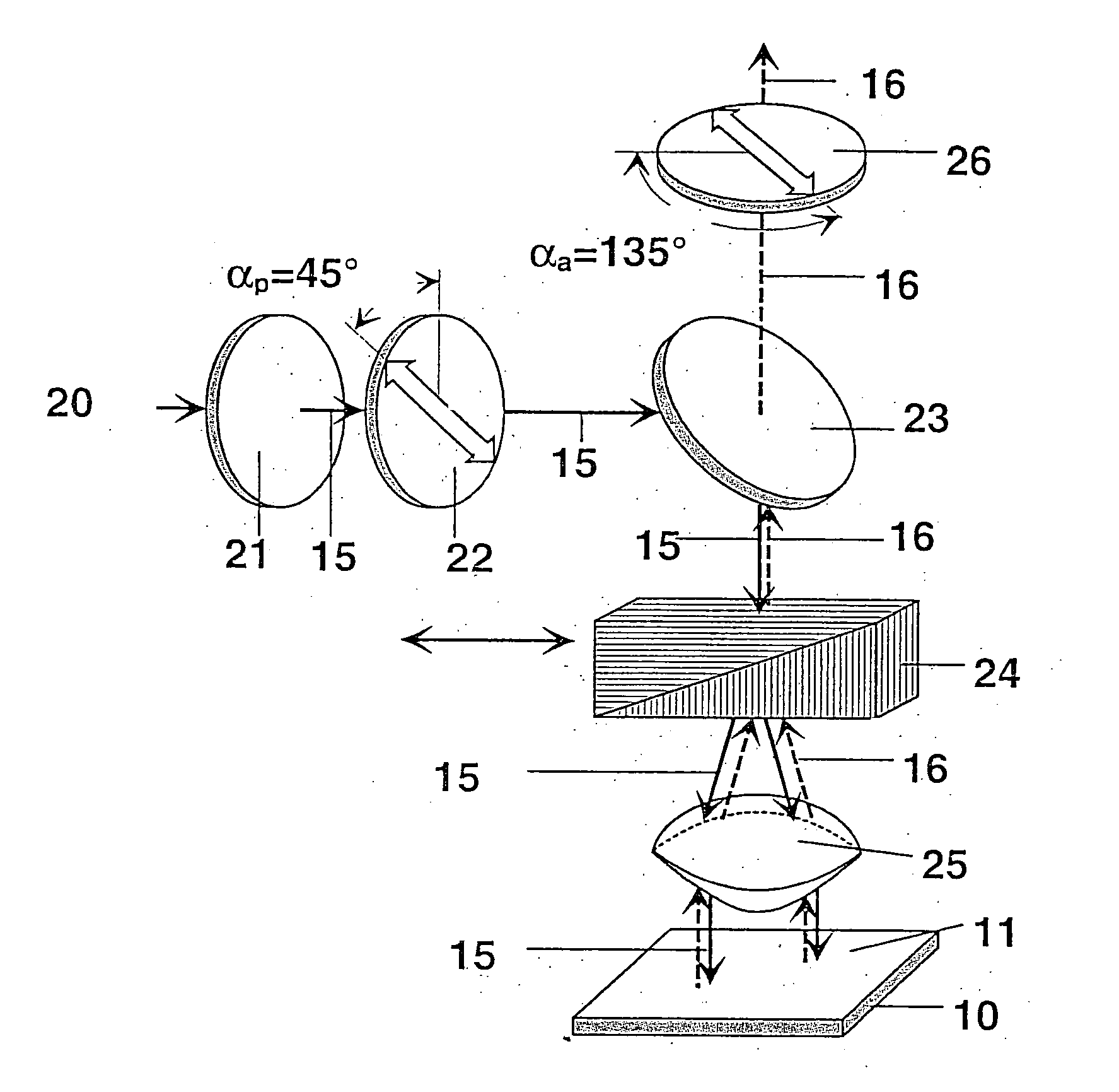
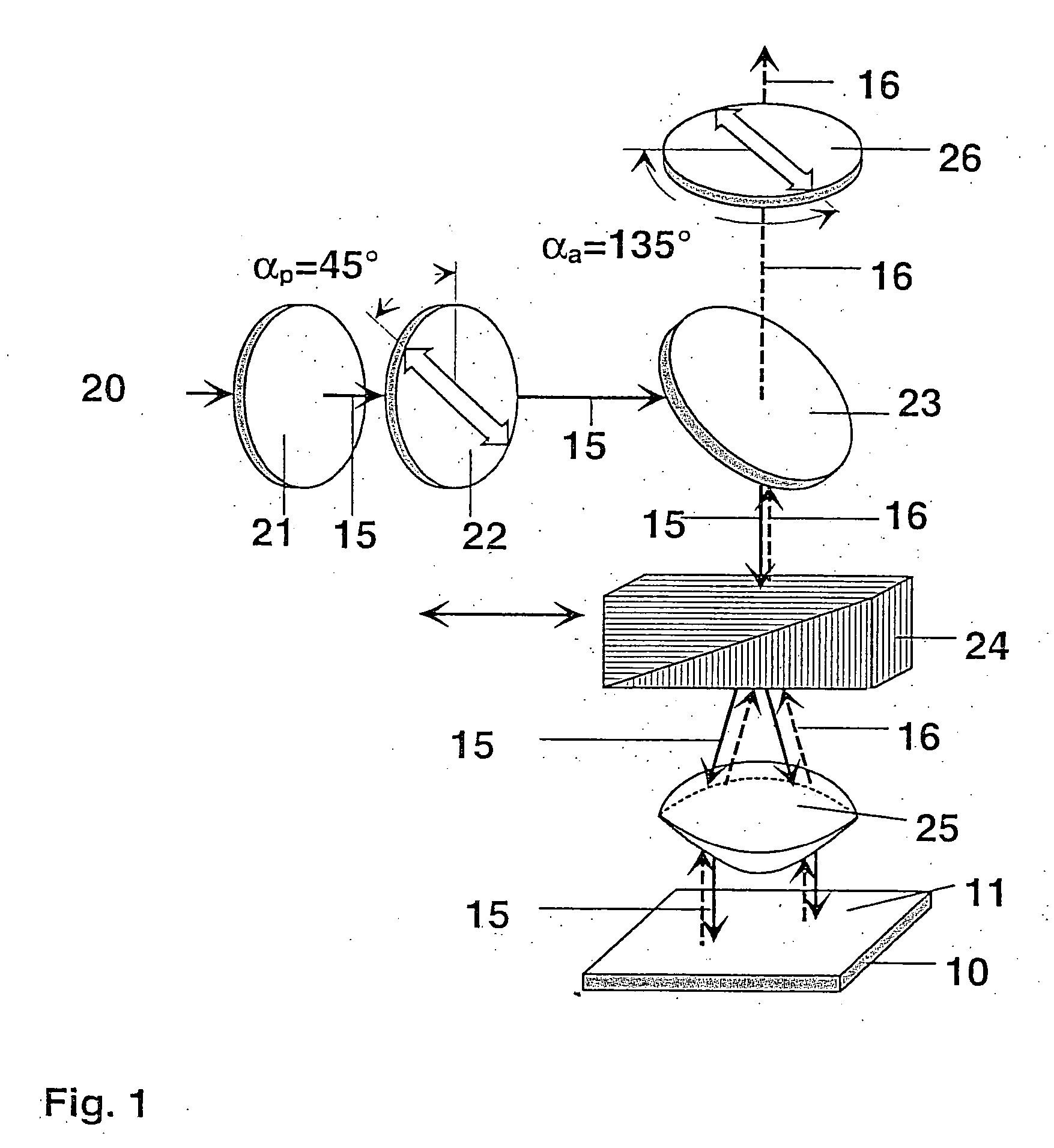
[0032]FIG. 1 schematically shows the setup of a microscope according to the invention. The overall structure of the microscope is similar to a Nomarski setup. A work piece 10 or the topography of the surface 11 of this work piece 10 is to be examined. The optical path is reproduced by initially incident light 15 and then light 16 reflected by the surface 11 of the work piece 10.

[0033] The starting point is a light source 20, which in the present embodiment is a white light source. The light preferably falls through a spectral filter 21 with a narrow frequency spectrum. The light of this frequency spectrum then strikes a polariser 22 and is linearly polarised there. The light then passes to a partially transparent, in this case semi-transparent, mirror 23, which is directed into the optical path in such a manner that it deflects the incident light from the light source 20 in the direction of the surface 11 of the work piece 10, in the present embodiment. The work piece is frequently...


PUM


Abstract

The invention relates to a microscope and a method for measuring the surface topography of a workpiece in a quantitative and optical manner. The invention includes a differential interference contrast microscope embodiment according to Nomarski, comprising a light source, a polariser, a changeable Nomarski prism and an analyser. The light source has a narrow frequency spectrum and / or is provided with a special filter having a narrow frequency spectrum; and the microscope is provided with a phase displacement interferometry evaluation unit.

Description

1. TECHNICAL FIELD [0001] The invention relates to a microscope and a method for the quantitative optical measurement of the topography of the surface of a work piece. 2. BACKGROUND OF RELATED ART [0002] Microscopes are not only used for viewing structures of small area more closely, but have also been used for a long time for the quantitative characterisation of surfaces. [0003] Reflected light interference microscopes are very easy to handle and operate without contact with the work piece, i.e. in an absolutely non-destructive manner. However, usual incident light techniques (bright field, dark field) are not suitable for examining the topographies of surfaces, since they are dependent on differences in amplitude on the surface. However, a surface topography does not generate any differences in amplitude, merely relative phase differences in the reflected wavefront. [0004] However, these phase differences may be converted into differences in amplitude by means of double-beam inter...

Claims


Application Information

Patent Timeline
Patent Type & Authority Applications(United States)
IPC IPC(8): G01B11/02
CPCG02B21/0016G01B9/04
Inventor TOBBEN, HELMUTSCHMITT, DIRK-ROGERRINGEL, GABRIELE
Owner CARL ZEISS SMT GMBH
Learn More