

Dual-type magnetic detecting element in which free magnetic layer and pinned magnetic layer have suitably selected β values
- Summary
- Abstract
- Description
- Claims
- Application Information
AI Technical Summary
Benefits of technology
Problems solved by technology
Method used
Image

Examples
first embodiment
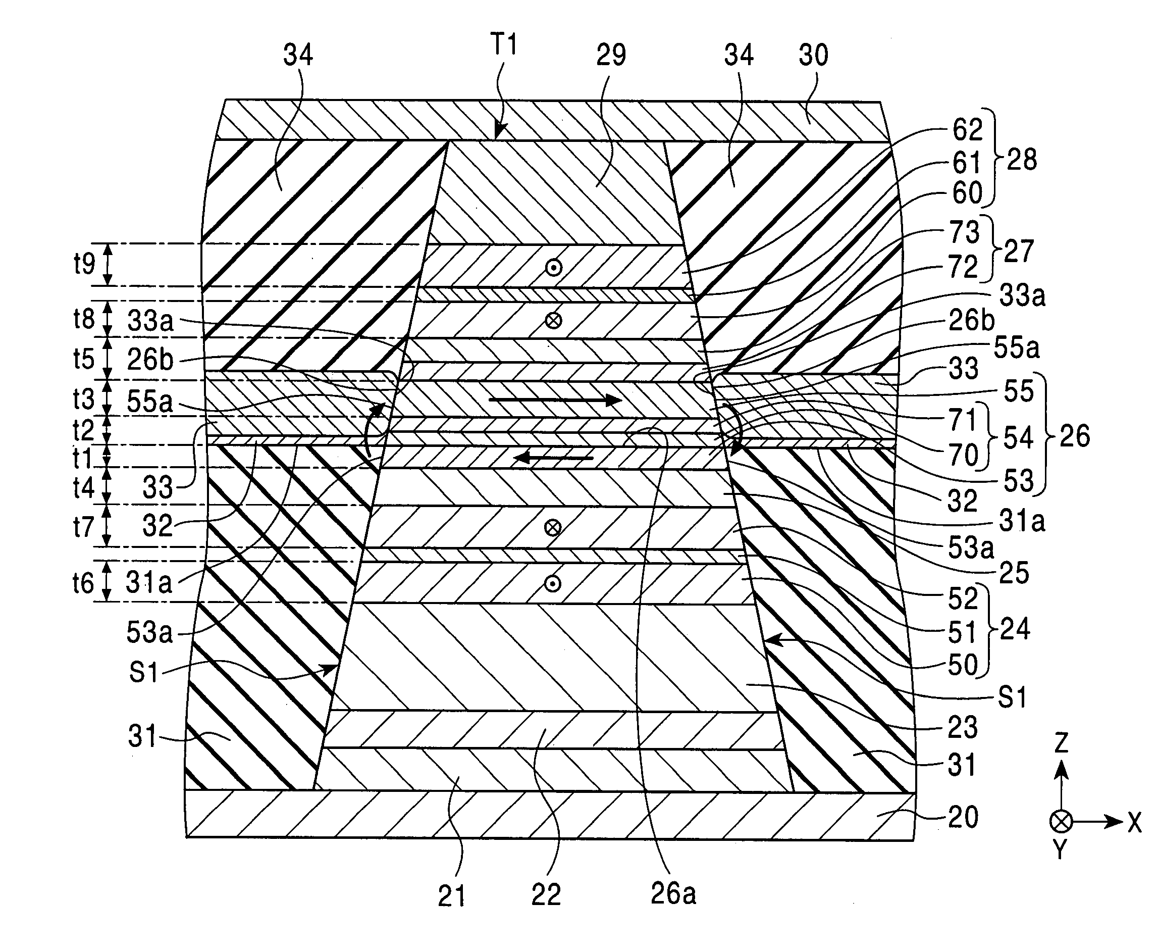
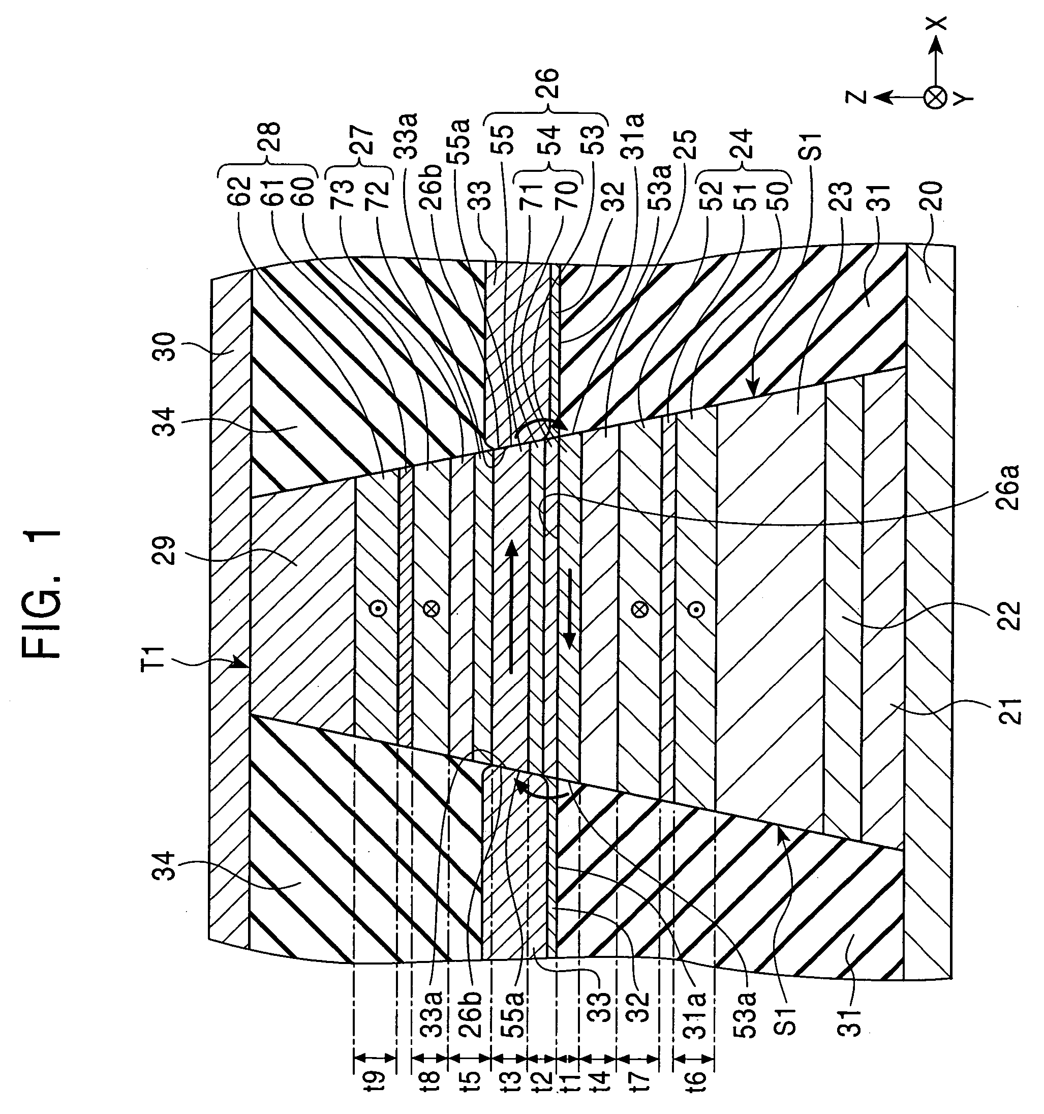
[0071]FIG. 1 is a fragmentary sectional view of the structure of a magnetic detecting element according to the present invention, viewed from a side opposing a recording medium.
[0072]The magnetic detecting element is a so-called dual spin-valve magnetic detecting element.
[0073]The magnetic detecting element include an underlayer 21, a seed layer 22, a lower antiferromagnetic layer 23, a lower pinned magnetic layer 24, having a three-layer ferrimagnetic structure composed of magnetic layers 50 and 52 and a nonmagnetic interlayer 51 formed of, for example, Ru between these magnetic layers, a lower nonmagnetic material layer 25 and a free magnetic layer 26, in that order, on the upper surface at the middle of a first electrode layer 20. The free magnetic layer 26 has a three-layer ferrimagnetic structure composed of first and second free magnetic layers 53 and 55 and a nonmagnetic interlayer 54 between these free magnetic layers. The magnetic detecting element further includes an upper...
case 1
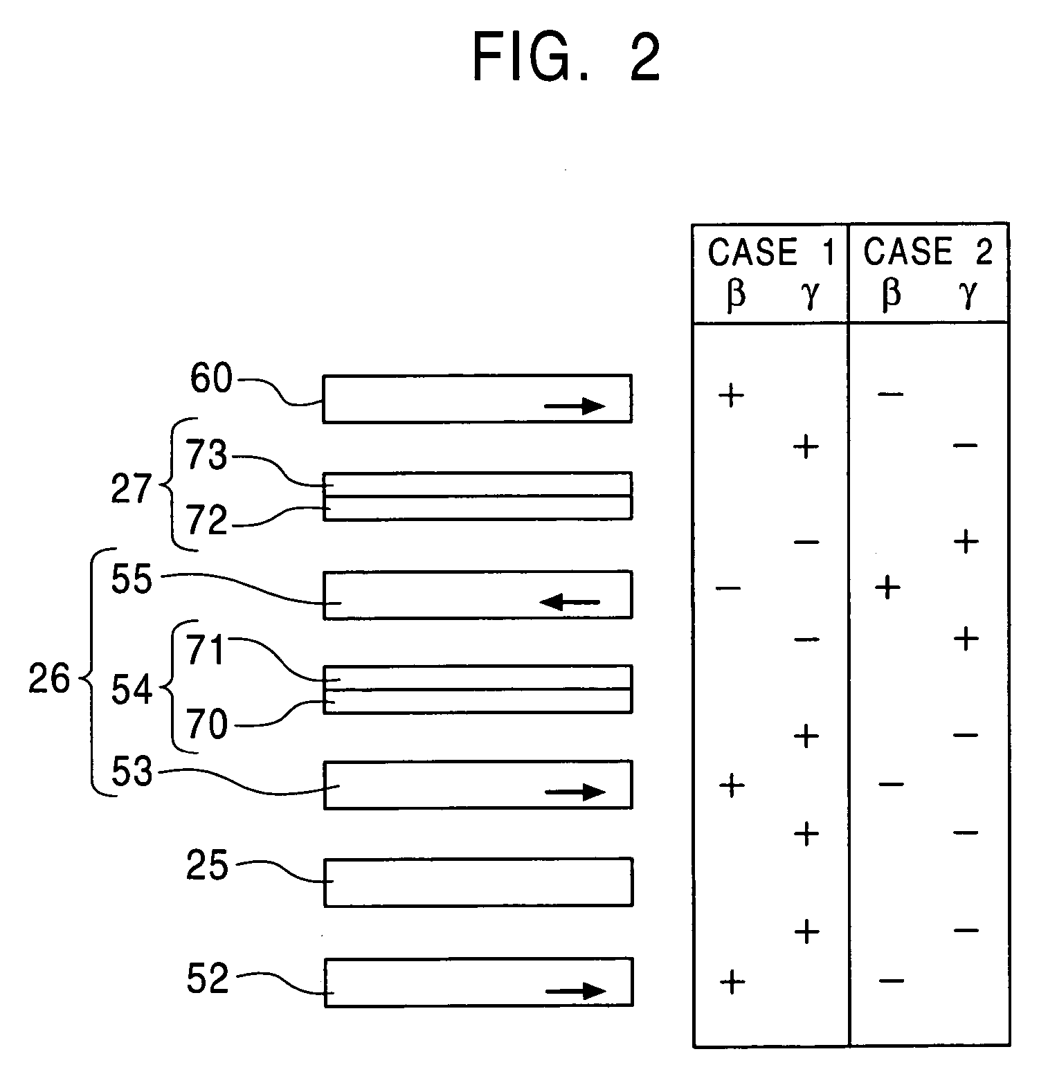
[0111]Case 1
[0112]The first free magnetic layer 53, the magnetic layer 52 of the lower pinned magnetic layer 24, the magnetic layer 60 of the upper pinned magnetic layer 28 are formed of a NiX alloy, a CoT alloy, a FeZ alloy, or a Co—Mn—D alloy, wherein X of the NiX alloy is an element selected from the group consisting of Co, Fe, Mn, Zr, Hf, Cu, and Au, T of the CoT alloy is an element selected from the group consisting of Fe, Zr, Ta, and Hf, Z of the FeZ alloy is an element selected from the group consisting of Ni, Co, Rh, Pt, Ir, Be, Al, Si, Ga, and Ge, and D of the Co—Mn—D alloy is an element selected from the group consisting of Al, Ga, Si, Ge, and Sn.
[0113]The second free magnetic layer 55 is formed of a NiM alloy, a CoQ alloy, or an FeA alloy, wherein M of the NiM alloy is an element selected from the group consisting of Cr, Rh, Ru, Mo, Nb, Pt, Ir, Os, Re, W, and Ta, Q of the CoQ alloy is an element selected from the group consisting of Mn, Cr, Ru, Mo, Ir, Os, Re, and W, and ...
case 2
[0115
[0116]The first free magnetic layer 53, the magnetic layer 52 of the lower pinned magnetic layer 24, and the magnetic layer 60 of the upper pinned magnetic layer 28 are formed of a NiM alloy, a CoQ alloy, or an FeA alloy, wherein M of the NiM alloy is an element selected from the group consisting of Cr, Rh, Ru, Mo, Nb, Pt, Ir, Os, Re, W, and Ta, Q of the CoQ alloy is an element selected from the group consisting of Mn, Cr, Ru, Mo, Ir, Os, Re, and W, and A of the FeA alloy is an element selected from the group consisting of Mn, Cr, V, Ti, Ru, Mo, Os, Re, and W
[0117]The second free magnetic layer 55 is formed of a NiX alloy, a CoT alloy, a FeZ alloy, or a Co—Mn—D alloy, wherein X of the NiX alloy is an element selected from the group consisting of Co, Fe, Mn, Zr, Hf, Cu, and Au, T of the CoT alloy is an element selected from the group consisting of Fe, Zr, Ta, and Hf, Z of the FeZ alloy is an element selected from the group consisting of Ni, Co, Rh, Pt, Ir, Be, Al, Si, Ga, and Ge...
PUM
 Abstract
Description
Claims
Application Information