Linear vibration motor
- Summary
- Abstract
- Description
- Claims
- Application Information
AI Technical Summary
Benefits of technology
Problems solved by technology
Method used
Image

Examples
first embodiment
The First Embodiment
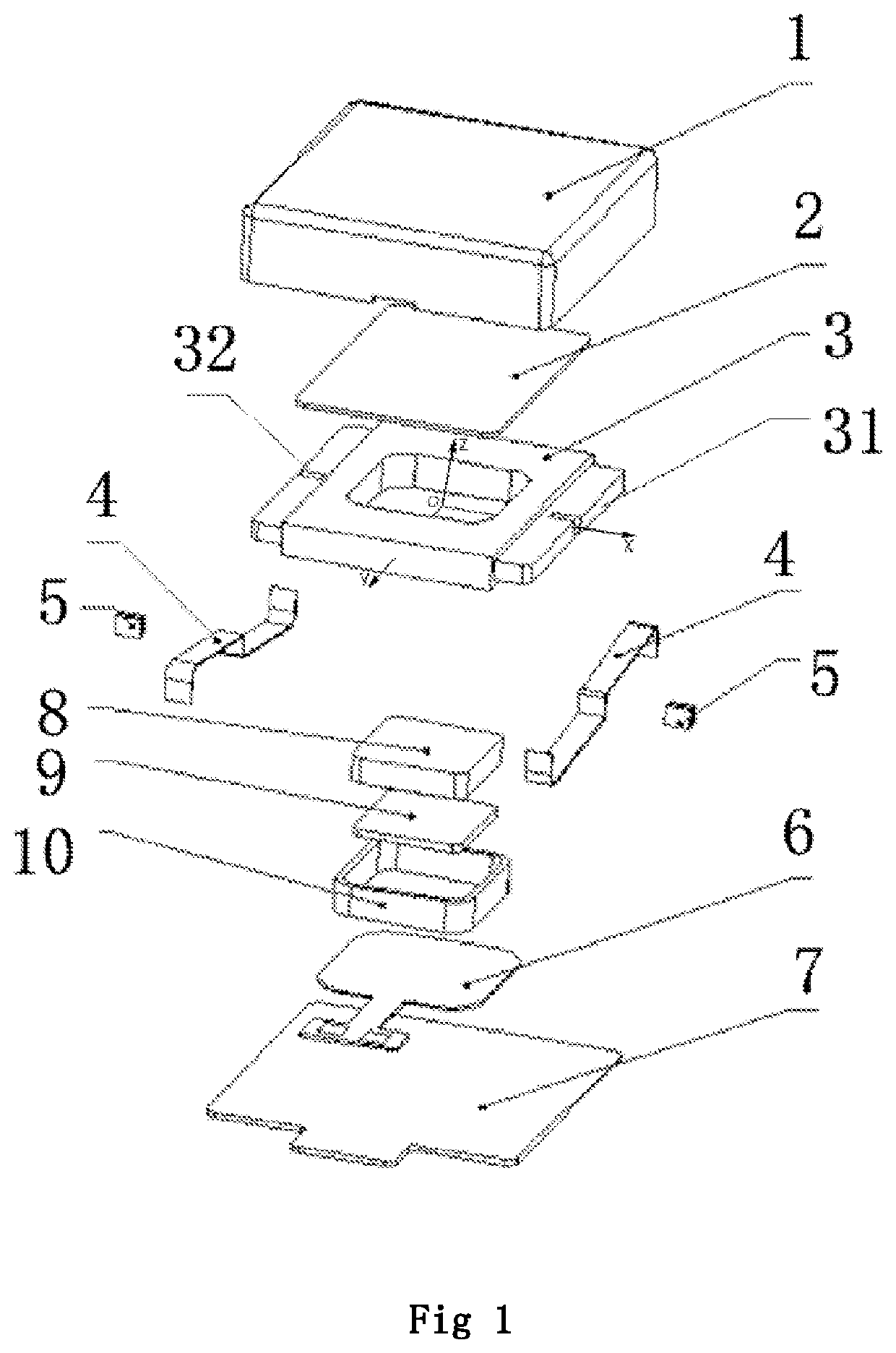
[0037]As shown in FIG. 1, an embodiment of the present invention provides a linear vibration motor comprising housing, a mass block 3, elastic pieces 4, a basin frame 2, an FPCB 6, a magnet, a washer, and a coil, wherein the housing comprises an upper shell 1 and a lower shell 7. The elastic pieces 4 connect the mass block 3 and the housing, and the elastic pieces 4 have at least two elastic pieces which are arranged on symmetrical two sides of the mass block 3 respectively to provide an elastic force in Z axis direction, and the mass block performs a movement up and down in the Z axis direction. The X, Y, and Z axis directions are shown in the coordinate system of FIG. 1, wherein the intersection point O of the X, Y, and Z axes is located at the center of the mass block (i.e., the geometric center of the mass block 3), and the Z axis is perpendicular to the upper surface of the mass block, and the X axis passes through the center of the elastic piece 4 (i.e., th...
second embodiment
The Second Embodiment
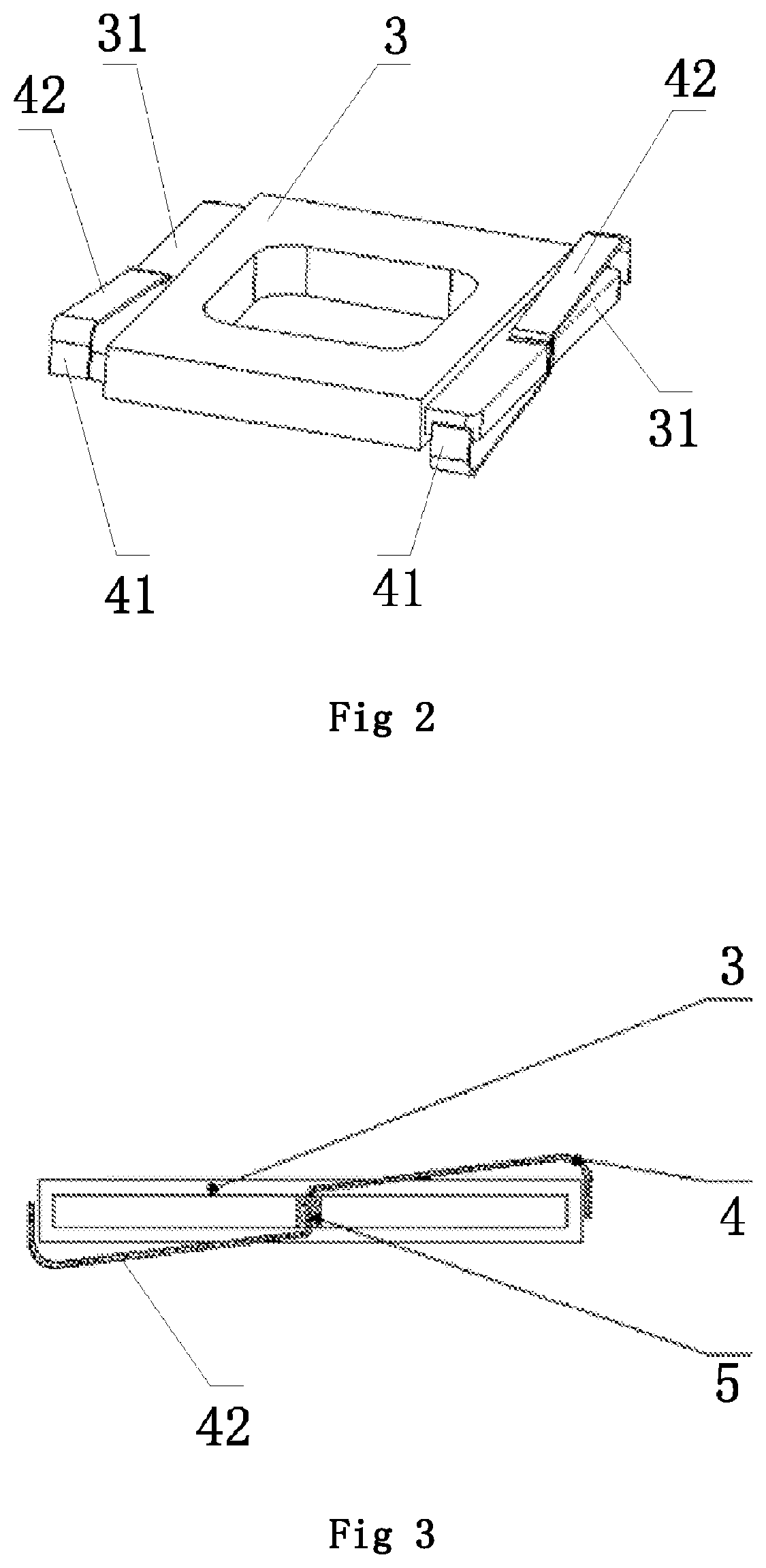
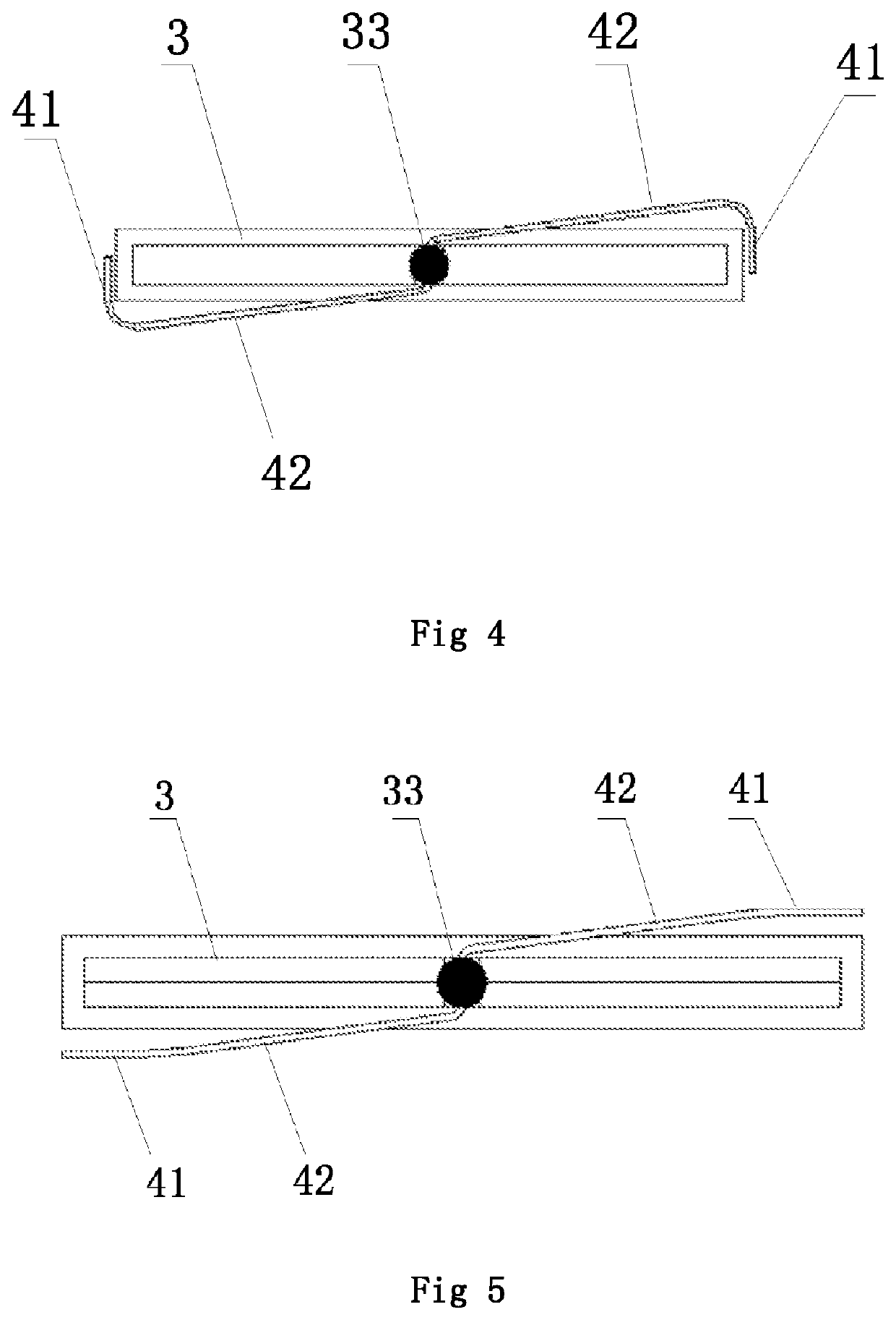
[0041]In the embodiment of the present invention, as shown in FIG. 5, the elastic pieces 4 are an anti-Z-shaped elastic piece 4, and the length of the elastic pieces 4 is not greater than the length of the support plate 31. The anti-Z-shaped elastic pieces 4 are provided with two vibration arms 42, and the two vibration arms 42 are symmetrical about the X axis when rotating 180 degrees around the X axis. The middle portion of the anti-Z-shaped elastic pieces 4 is welded and fixed in the notch 32 of the support plate 31, and the two vibration arms 42 are respectively located on the upper side and the lower side of the support plate 31. The free ends of the two vibration arms 42 are provided with welding planes 41, and the welding planes 41 are parallel to the plane in the longitudinal direction of the support plate 31. The two vibration arms 42 are fixed in the housing by welding each of the welding planes 41.
[0042]In the embodiment of the present invention, the ...
third embodiment
The Third Embodiment
[0043]In the embodiment of the present invention, as shown in FIG. 6 and FIG. 7 together, the elastic piece 4 is composed of two V-shaped vibration arms 42 and one connecting piece 43, the V-shaped vibration arm 42 are integrally formed with the connecting piece 43, and the length of the V-shaped vibration arm 42 is not greater than ½ of the length of the support plate 31. The two V-shaped vibration arms 42 are symmetrical about the Z axis when rotating 180 degrees around the Z axis, and the openings of the two V-shaped vibration arms 42 are opposite to each other. The connecting piece 43 of the elastic piece 4 is fixed in the notch 32, and the two V-shaped vibration arms 42 are respectively located on the upper side and the lower side of the support plate 31. The free ends of the two V-shaped vibration arms 42 are provided with welding planes 41, and the two V-shaped vibration arms 42 are respectively fixed in the housing by welding the welding planes 41.
[0044]I...
PUM
 Abstract
Description
Claims
Application Information
 - Generate Ideas
- Intellectual Property
- Life Sciences
- Materials
- Tech Scout
- Unparalleled Data Quality
- Higher Quality Content
- 60% Fewer Hallucinations
Browse by: Latest US Patents, China's latest patents, Technical Efficacy Thesaurus, Application Domain, Technology Topic, Popular Technical Reports.
© 2025 PatSnap. All rights reserved.Legal|Privacy policy|Modern Slavery Act Transparency Statement|Sitemap|About US| Contact US: help@patsnap.com