Information recording apparatus

a technology of information recording and recording equipment, which is applied in the direction of digital signal error detection/correction, instruments, recording signal processing, etc., can solve the problems of significant errors in the accuracy of each of the above-mentioned power control, affecting the accuracy of servo control, and affecting the accuracy of each of the above power control. achieve the effect of high accuracy and highly accurate power adjustmen

Inactive Publication Date: 2007-01-16
PIONEER CORP
View PDF12 Cites 66 Cited by
  • Summary
  • Abstract
  • Description
  • Claims
  • Application Information

AI Technical Summary

Benefits of technology

[0026]The present invention was developed in view of these prior-art problems. It is therefore an object of the invention to provide an information recording apparatus which provides control to the power emitted from its light source and various types of servo control with higher accuracy, for example, upon writing information at high speeds.
[0027]To achieve the aforementioned object, the present invention provides an information recording apparatus for writing information onto an information storage medium using a light beam emitted from a light source. The information recording apparatus includes: a first detection unit for detecting a power of a light beam emitted from the light source; a second detection unit for detecting an on-track condition and an in-focus condition of the light beam relative to the information storage medium; a first generation unit for generating a detection signal indicative of a variation in power of the light beam on the basis of a detection signal output from the first detection unit; a second generation unit for generating a tracking error signal on the basis of a detection signal output from the second detection unit; a third generation unit for generating a focus error signal on the basis of a detection signal output from the second detection unit; a first control unit for adjusting the power of the light beam emitted from the light source on the basis of the detection signal generated by the first generation unit; a second control unit for performing tracking servo on the basis of the tracking error signal generated by the second generation unit; and a third control unit for performing focus servo on the basis of the focus error signal generated by the third generation unit. The first control unit samples and holds the detection signal generated by the first generation unit, in sync with a timing delayed by a time corresponding to a delay time of the first generation unit, and adjusts the power of the light beam on t

Problems solved by technology

However, the prior art servo systems APC and FT shown in FIG. 7 had a problem that increasing the frequency fck of the clock signal CK to write information at higher speeds (i.e., shortening the period 1/fck) would degrade the accuracy in servo control.
This made it difficult to properly extract information about power variations, tracking error, and focus error even when the sample and hold circuits 4, 8, and 9 sample and hold each of the detection signal Vapc, the tracking error signal Ste, and the focus error signal Sfe in sync with the sample and hold signal SH

Method used


Image

  • Information recording apparatus
  • Information recording apparatus
  • Information recording apparatus

Examples


Embodiment Construction

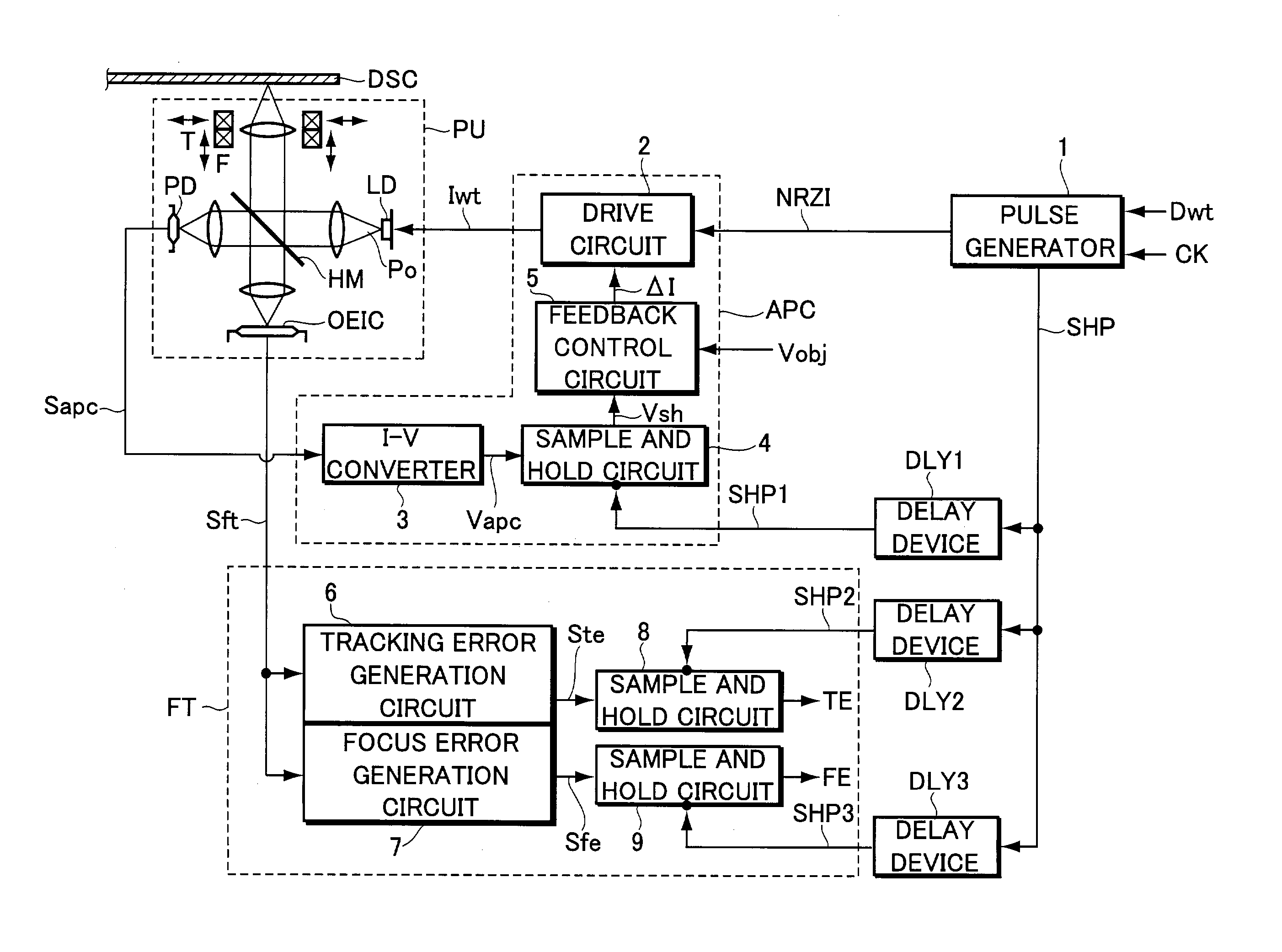
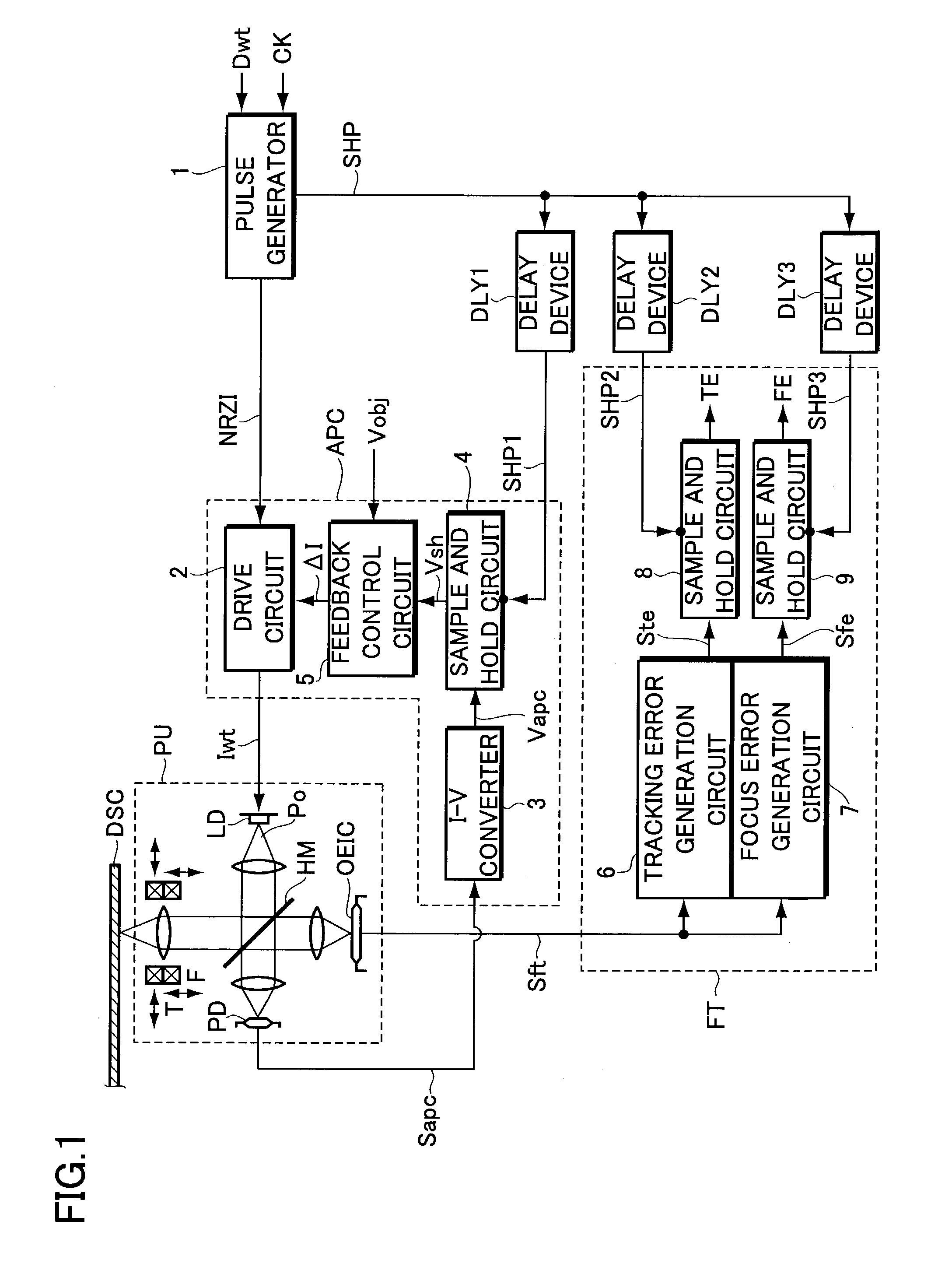
[0041]Now, the present invention will be explained with reference to the accompanying drawings in accordance with one of embodiments. FIG. 1 is a block diagram illustrating the configuration of an information recording apparatus according to the embodiment.

[0042]Referring to FIG. 1, the information recording apparatus includes a pickup PU for optically writing information onto a write-once information storage medium or a rewritable (e.g., phase change) information storage medium, a power control system APC for controlling the power of light beams emitted from a semiconductor laser LD serving as a light source incorporated into the pickup PU, and a focus tracking servo system FT for performing focus servo and tracking servo. The apparatus further includes a system controller (not shown) having a microprocessor (MPU) for intensively managing and controlling the operation of the information recording apparatus.

[0043]For example, when data to be recorded such as movie or music data is s...


PUM


Abstract

An information recording apparatus is provided, which can control over the power of light beams emitted from a light source and various types of servo control with higher accuracy. A laser beam is emitted from a semiconductor laser to write information onto an optical disc. A detection signal indicative of the power of the laser beam output from a light-receiving device is sampled and held with a sample and hold circuit via an I-V converter at a timing delayed by the time corresponding to the delay time of the I-V converter. A tracking error generation circuit and a focus error generation circuit generate a tracking error signal and a focus error signal, respectively, on the basis of a detection signal having information about tracking error and focus error and output from a light-receiving device. Sample and hold circuits sample and hold the tracking error signal and the focus error signal at a timing delayed by the time corresponding to the delay time of each of the generation circuits, respectively. Power control, tracking servo, and focus servo are performed using each of the signals held by the sample and hold circuits, respectively.

Description

BACKGROUND OF THE INVENTION[0001]The present invention relates to an information recording apparatus which utilizes light beams to write information onto information storage media.[0002]The present application claims priority from Japanese Application No. 2002-165779, the disclosure of which is incorporated herein by reference.[0003]A conventional information recording apparatus for writing information onto a write-once or rewritable information storage medium (hereinafter generally referred to as an “optical disc”) includes various types of servo systems APC and FT as shown in the block diagram illustrated in FIG. 7.[0004]The servo system APC provides feedback control on the power supplied to a semiconductor laser LD provided in a pickup PU, in order to set the laser beam (hereinafter referred to as a “write laser beam”) Po emitted from the semiconductor laser LD at a predetermined target value.[0005]The servo system FT performs focus servo and tracking servo to properly illuminate...

Claims


Application Information

Patent Timeline
IPC IPC(8): G11B7/125G11B7/09G11B7/0045G11B7/1263
CPCG11B7/09G11B7/1263G11B7/0045G11B7/0908G11B7/0901
Inventor TATEISHI, KIYOSHIFURUKAWA, JUNICHI
Owner PIONEER CORP
Why Eureka
Try Eureka