
Method and apparatus for writing and reading servo information written in a spiral fashion

Inactive Publication Date: 2007-01-23
MAXTOR
View PDF20 Cites 31 Cited by
  • Summary
  • Abstract
  • Description
  • Claims
  • Application Information

AI Technical Summary

Benefits of technology

[0023]The present invention is designed to meet the aforementioned, and other, needs. The invention is directed to a method and apparatus for writing spiral servo information onto one or more disk surfaces at a variable velocity using a servo track writer (STW). In one embodiment, a variable velocity profile is chosen so that spiral crossing ang

Problems solved by technology

In general, a STW is a very expensive piece of capital equipment.
Even a small reduction in the amount of data needed to be written by the STW per disk surface can result in a significant cost and time savings.
However, as alluded to above, the purchase of additional servo track writers involves a significant capital expense.
However, writing spiral servo patterns at a constant velocity may require certain tradeoffs.

Method used


Image

  • Method and apparatus for writing and reading servo information written in a spiral fashion
  • Method and apparatus for writing and reading servo information written in a spiral fashion
  • Method and apparatus for writing and reading servo information written in a spiral fashion

Examples


Embodiment Construction

[0043]While this invention is susceptible of embodiments in many different forms, there are shown in the drawings and will herein be described in detail, preferred embodiments of the invention with the understanding that the present disclosure is to be considered as an exemplification of the principles of the invention and is not intended to limit the broad aspects of the invention to the embodiments illustrated.

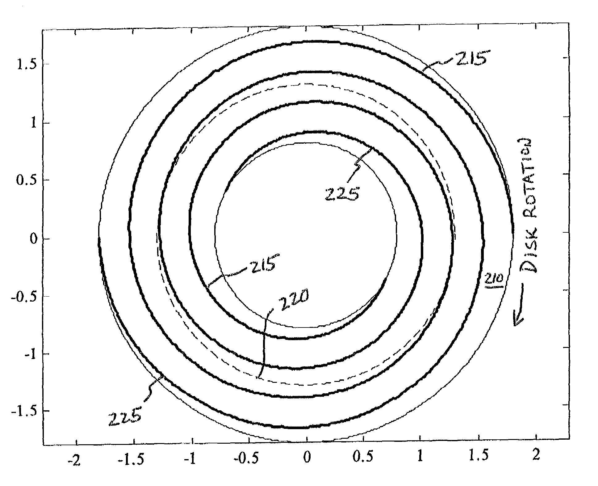
[0044]FIG. 7 is a diagrammatic representation of a disk surface 210 having a first spiral of servo information 215 written thereon in accordance with the present invention. The dashed line, identified by reference numeral 220, represents a track. The first spiral of servo information 215 may make multiple revolutions around the disk surface 210 (roughly two revolutions as shown in FIG. 7), but only crosses track 220 once.

[0045]FIG. 8 is a diagrammatic representation of a disk surface 210 having a first spiral of servo information 215 and a second spiral of servo information ...


PUM


Abstract

A method and apparatus for writing spiral servo information onto one or more disk surfaces at a variable velocity using a servo track writer (STW) is provided. In one embodiment, a variable velocity profile is chosen so that spiral crossing angles across the disk surface are set to be equal. In another embodiment, a variable velocity profile is chosen so that spiral crossing angles across groups of tracks (i.e., two or more tracks) are set to be equal. In yet another embodiment, a variable velocity profile is chosen to adjust the number of tracks per inch (TPI) across the disk surface.

Description

CROSS-REFERENCE TO RELATED APPLICATIONS[0001]Priority is claimed from U.S. Provisional Patent Application Ser. No. 60 / 285,055 filed Apr. 19, 2001, which is incorporated by reference herein in its entirety. This is a continuation-in-part of U.S. patent application Ser. No. 09 / 853,093 now abandoned, filed May 9, 2001, which claims priority from U.S. Provisional Patent Application Ser. No. 60 / 203,159 filed May 9, 2000, U.S. Provisional Patent Application Ser. No. 60 / 223,446 filed Aug. 4, 2000, and U.S. Provisional Patent Application Ser. No. 60 / 285,055 filed Apr. 19, 2001. All of the aforementioned patent applications are specifically incorporated herein by reference in their entireties.INCORPORATION BY REFERENCE[0002]U.S. patent application Ser. No. 09 / 923,570 filed Aug. 6, 2001 is specifically incorporated herein by reference in its entirety.FIELD OF THE INVENTION[0003]The present invention relates to computer disk drives. More particularly, the present invention relates to writing s...

Claims


Application Information

Patent Timeline
IPC IPC(8): G11B21/02
CPCG11B5/5526G11B5/59661G11B5/59633
Inventor LIIKANEN, BRUCE A.RIGNEY, BRIAN P.
Owner MAXTOR
Learn More