Prosthetic foot with cam

a technology of prosthetic feet and cams, applied in the field of prosthetic feet, can solve the problems of limited amount of energy storage, limitations introduced, and typical prosthetic feet utilizing springs limited to energy storag

Active Publication Date: 2007-02-06
FREEDOM INNOVATIONS INC
View PDF118 Cites 66 Cited by
  • Summary
  • Abstract
  • Description
  • Claims
  • Application Information

AI Technical Summary

Benefits of technology

[0008]It has been recognized that it would be advantageous to develop a prosthetic foot that enables energy storage within, and release from, the foot in a nonlinear, maximized manner.

Problems solved by technology

While each of these variations has added some benefit to the field of energy storing prosthetic feet, they have often met with limitations introduced by the general nature of springs.
Thus, typical prosthetic feet utilizing springs have been limited to storage of energy in the spring in an amount that corresponds to a constant multiple of the distance over which the spring was compressed or stretched.
This has resulted in a limited amount of energy being storable in the spring and does not effectively leverage the energy expended by a user of the prosthetic foot.

Method used


Image

  • Prosthetic foot with cam
  • Prosthetic foot with cam
  • Prosthetic foot with cam

Examples


Embodiment Construction

[0030]Reference will now be made to the exemplary embodiments illustrated in the drawings, and specific language will be used herein to describe the same. It will nevertheless be understood that no limitation of the scope of the invention is thereby intended. Alterations and further modifications of the inventive features illustrated herein, and additional applications of the principles of the inventions as illustrated herein, which would occur to one skilled in the relevant art and having possession of this disclosure, are to be considered within the scope of the invention.

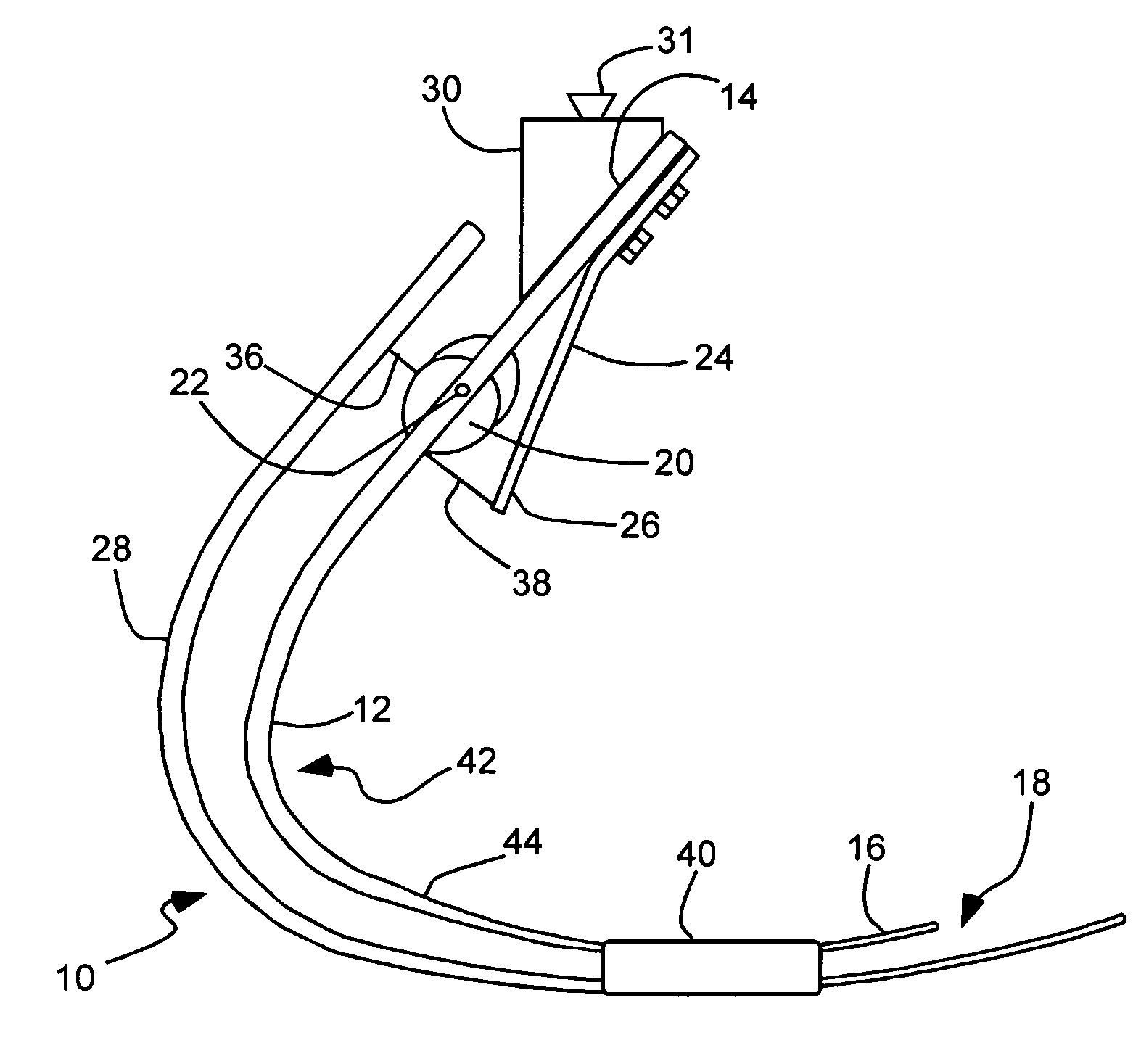
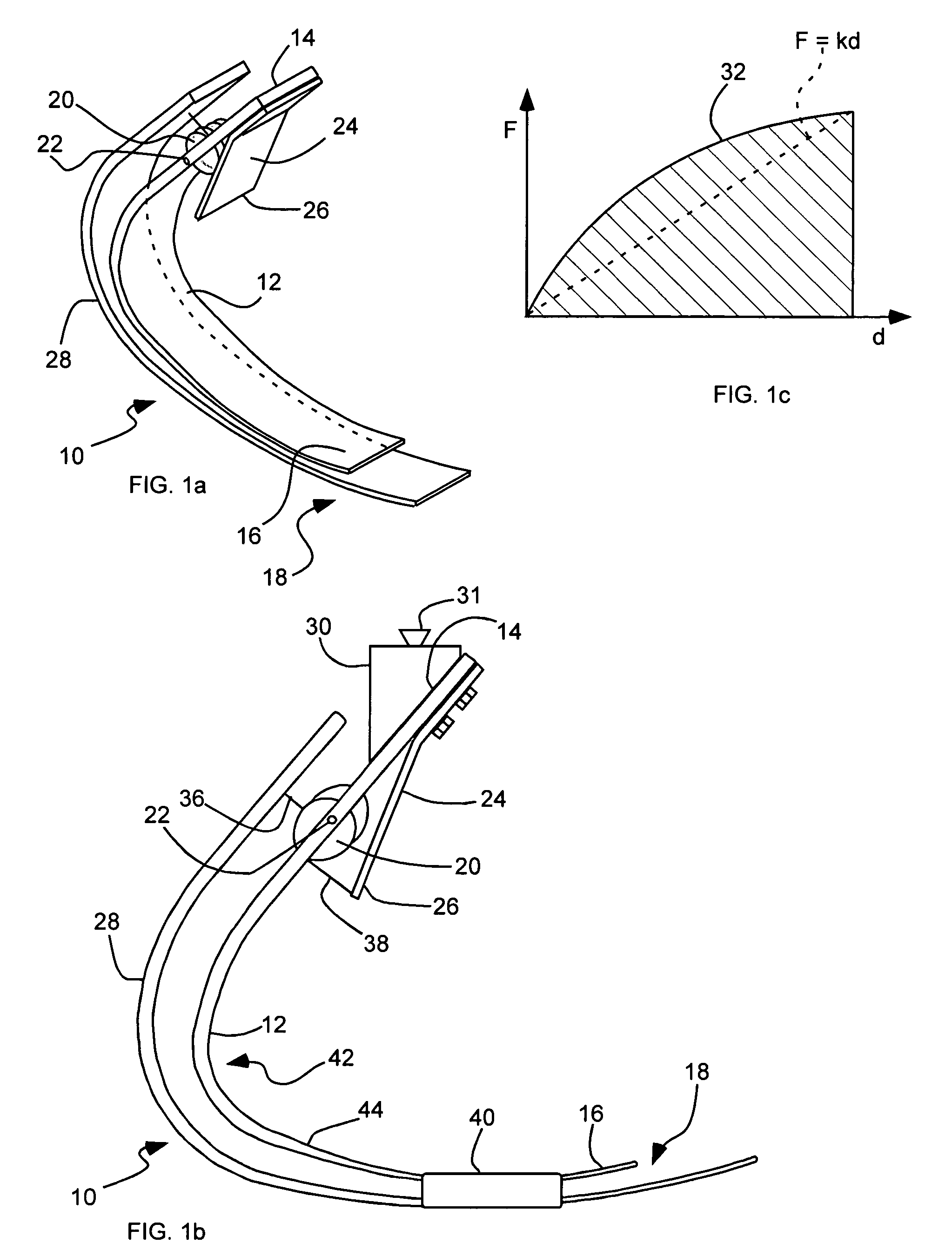
[0031]As illustrated in FIGS. 1a and 1b, a prosthetic foot or prosthetic foot device, indicated generally at 10, in accordance with the present invention is shown for use with an amputee. The prosthetic foot 10 can include a plurality of cantilever-springs that elastically deform under a load to store and release energy, and that are operatively inter-coupled to have a non-linear force versus deflection relations...


PUM


Abstract

A prosthetic foot device includes an elongated continuous cantilever-spring, extending from an attachment section coupleable to a stump of an amputee to a toe section at a toe location of a natural foot. The cantilever-spring is elastically deformable under a load to store energy as the amputee steps onto the cantilever-spring and to release energy as the amputee steps off of the cantilever-spring. A cam is pivotally coupled to the cantilever-spring at a pivot. A resistance arm is coupleable to the stump of the amputee, and extends to a displaceable section engaging the cam. A lever arm is attached to the cantilever-spring and engages the cam. The cam operatively inter-couples the cantilever-spring and the resistance arm to elastically deform the resistance arm along with the cantilever-spring to collectively store more energy than the cantilever-spring alone.

Description

BACKGROUND OF THE INVENTION[0001]1. Field of the Invention[0002]The present invention relates generally to prosthetic feet. More particularly, the present invention relates to a prosthetic foot with a plurality of cantilever-springs inter-coupled to have a non-linear force versus deflection relationship and to store more energy together than alone.[0003]2. Related Art[0004]Many individuals have lost a limb for various reasons such as war, accident, or disease. In most instances these individuals are not only able to live relatively normal lives, but are able to lead physically active lives as well. Oftentimes, these individuals are aided in their everyday lives by a prosthetic limb. Prosthetic limbs, or prosthesis, generally provide an artificial limb that simulates the function and natural feel of the lost limb.[0005]With respect to prosthetic feet, the development of functional and natural artificial feet has been pursued for some time. Many designs have attempted to copy the anat...

Claims


Application Information

Patent Timeline
Patent Type & Authority Patents(United States)
IPC IPC(8): A61F2/66A61F2/68A61F2/00A61F2/50
CPCA61F2/66A61F2002/30462A61F2002/30476A61F2002/30518A61F2002/503A61F2002/5033A61F2220/0075A61F2002/6614A61F2002/6664A61F2002/6671A61F2002/6678A61F2220/0025A61F2002/5093
Inventor CHRISTENSEN, ROLAND J.
Owner FREEDOM INNOVATIONS INC
Why Eureka
Try Eureka