Performing measurement or calibration on positioning machines

a positioning machine and measurement technology, applied in the field of machines, can solve problems such as and achieve the effect of reducing the movement of the machin

Inactive Publication Date: 2007-02-13
RENISHAW PLC
View PDF48 Cites 8 Cited by
  • Summary
  • Abstract
  • Description
  • Claims
  • Application Information

AI Technical Summary

Problems solved by technology

A problem with the apparatus described in the various above-referenced patent applications is that of calibrating the movement of the machine.

Method used


Image

  • Performing measurement or calibration on positioning machines
  • Performing measurement or calibration on positioning machines
  • Performing measurement or calibration on positioning machines

Examples


Embodiment Construction

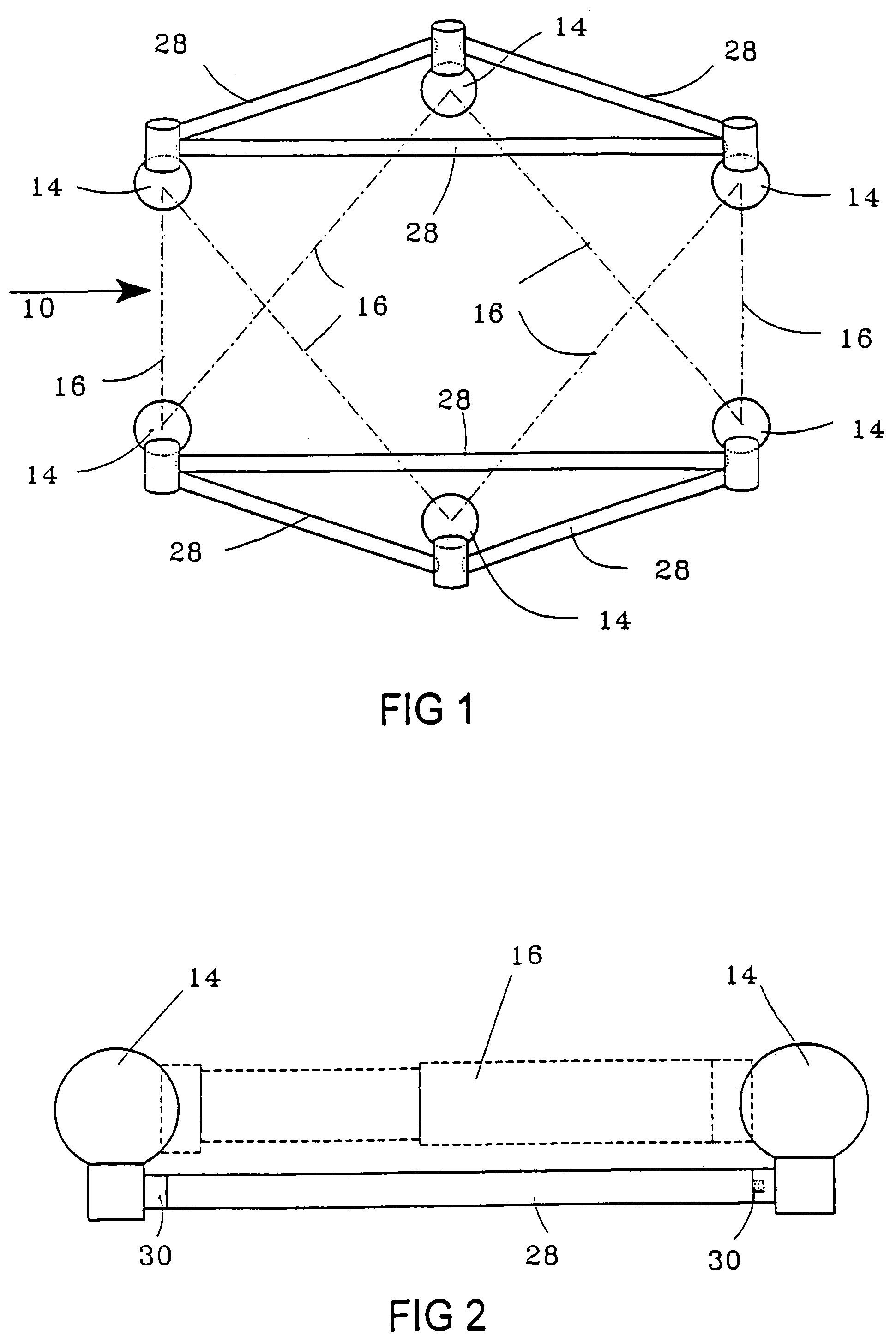
[0038]FIG. 1 shows a device which can be used for calibration. It comprises an upper structure in the form of an open triangular frame 10 and a lower structure in the form of an open triangular frame 12. Each frame is provided with three precision steel balls 14, one at each corner of the triangle. In use, the upper frame 10 is clamped to the moving structure of a machine, while the lower frame is clamped to the fixed structure (or vice versa). The device may be used with conventional machine tools or with the types of machines illustrated in the above-referenced International and European applications.

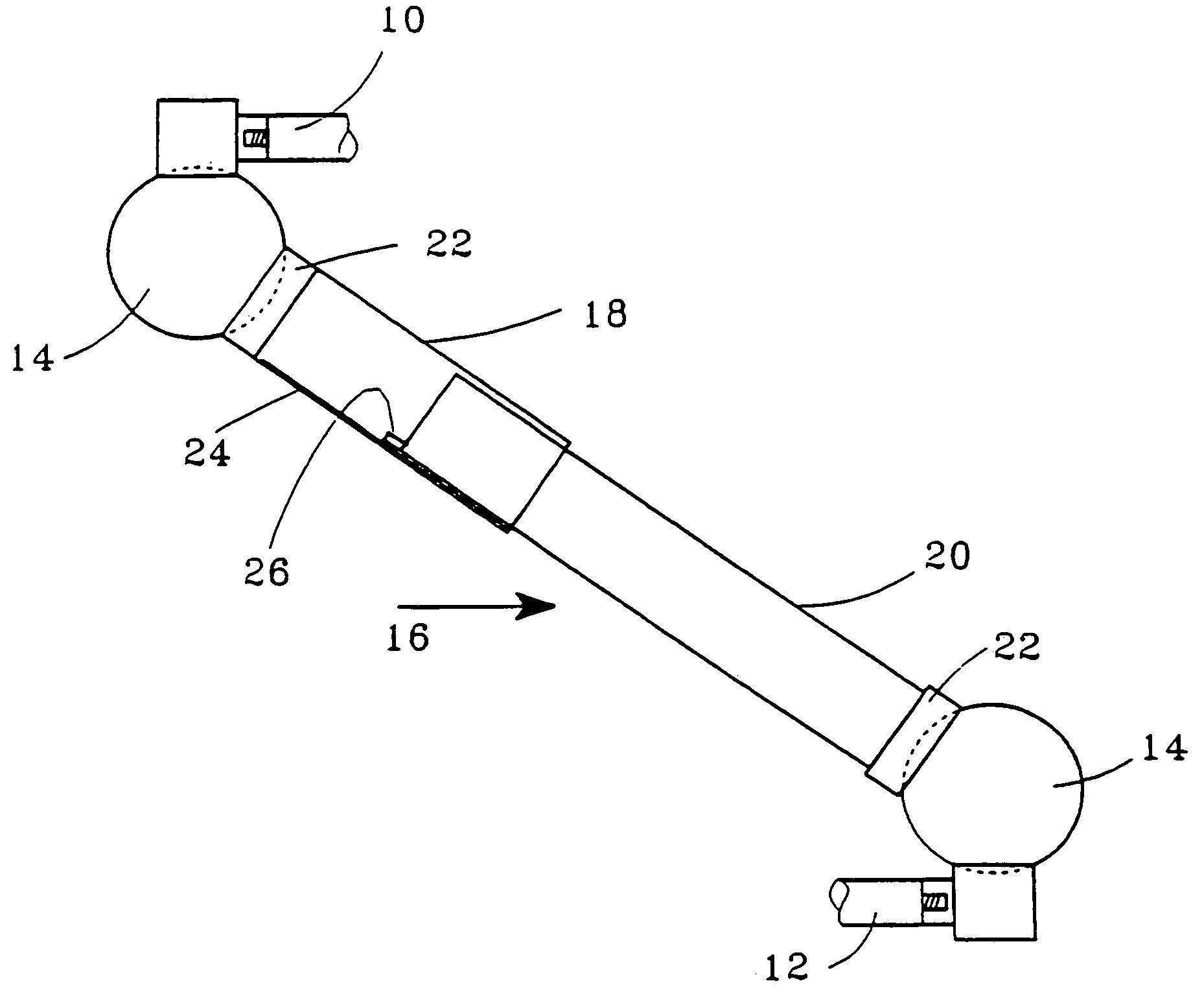
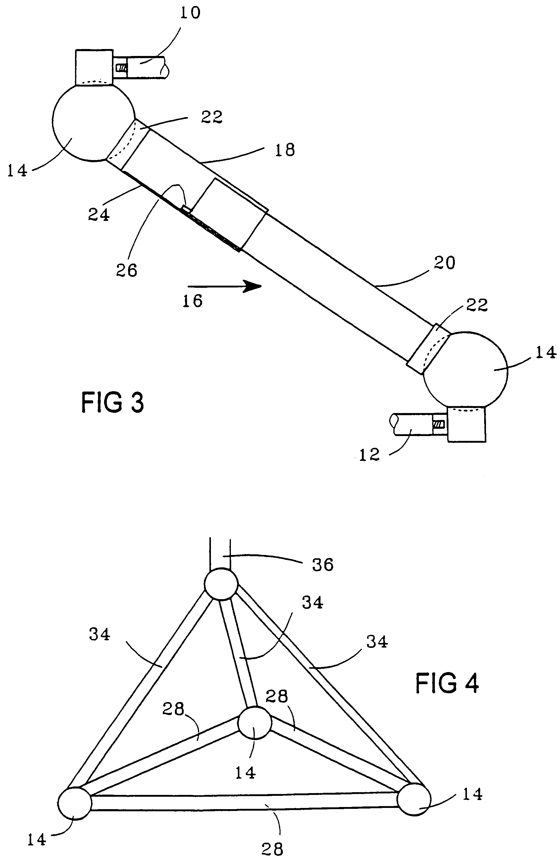
[0039]The spheres 14 are linked in use by six members which in this embodiment are passive measuring bars 16. The positions of these are shown merely by broken lines in FIG. 1, but more detail is seen in FIG. 3. Each measuring bar 16 in this example comprises parts 18,20 which interfit telescopically and extend between the spheres, but may take the form of rigid links which pass throu...


PUM


Abstract

A machine having a pair of spaced structures, a plurality of ball and socket joints spaced apart on each structure, and six struts interconnecting the structures. Each strut engages with a respective ball and socket joint on each of the structures, and defines a variable distance between the centers of the ball and socket joints to which the strut is connected. At least one of the ball and socket joints to which the strut is connected has a plurality of the struts connected thereto, the ball and socket joint having a socket on each respective strut, co-operating with a sphere, the sockets having three engagement elements biased into engagement with the sphere.

Description

[0001]This is a Divisional Application of application Ser. No. 10 / 462,606, filed Jun. 17, 2003 now U.S. Pat. No. 6,918,188, which is a Continuation Application of application Ser. No. 10 / 261,410, filed Oct. 2, 2002 now U.S. Pat No. 6,662,461, which is a Continuation Application of application Ser. No. 09 / 803,917, filed Mar. 13, 2001 now abandoned, which is a Division of application Ser. No. 08 / 886,062, filed Jul. 3, 1997 now U.S. Pat. No. 6,226,884, which in turn is a Rule 60 Continuation Application of U.S. patent application Ser. No. 08 / 530,247, filed Oct. 30, 1995 now U.S. Pat. No. 5,681,981, which in turn is a U.S. National Stage filing under 35 U.S.C. §371 of International Application No. PCT / GB95 / 00169, filed Jan. 27, 1995. The entire disclosures of the prior applications are hereby incorporated by reference herein in their entirety.BACKGROUND OF THE INVENTION[0002]This invention relates to machines in which one member is positioned relative to another. For example, it relates...

Claims


Application Information

Patent Timeline
Patent Type & Authority Patents(United States)
IPC IPC(8): G01B3/16G01B21/02B23Q1/44G05G1/01B23Q1/54B23Q17/22G01B3/30G01B5/08G01B7/00G01B21/00G01B21/04G05B19/401
CPCB23Q1/5462B23Q17/2233G01B21/042G05B19/401G01B3/30Y10T74/20213
Inventor MCMURTRY, DAVID R.
Owner RENISHAW PLC
Why Eureka
Try Eureka