Supercharge Your Innovation With Domain-Expert AI Agents!

Keyless chuck and associated method

a keyless chuck and associated technology, applied in the field of drill chucks, can solve the problems of unusable keyed drill chucks, damage to workpieces, operator injury,

Inactive Publication Date: 2007-02-20
YUKIWA SEIKO
View PDF30 Cites 10 Cited by
  • Summary
  • Abstract
  • Description
  • Claims
  • Application Information

AI Technical Summary

Benefits of technology

The design ensures secure and reliable operation of the chuck by preventing accidental disengagement of components, minimizing risk of damage or injury, and simplifying assembly and disassembly processes, while maintaining a clean and aesthetically pleasing appearance.

Problems solved by technology

However, such a keyed drill chuck requires manual tightening and loosening of the jaws with the chuck key, wherein the chuck key may be easily lost or misplaced, thereby disadvantageously rendering the keyed drill chuck unusable.
Such a mechanism may be complex, often requiring multiple cooperating parts.
However, heretofore, one of the challenges with keyless drill chucks has been appropriately securing the one or more sleeves in proper position about the mechanism and the body, while allowing the one or more sleeves to have the necessary operability for implementing the function of the mechanism, and while allowing the chuck to be readily assembled and disassembled.
However, external fasteners may disadvantageously be prone to accidental disengagement during use of the chuck, the fastener may become unsecured and lost, may cause damage to the workpiece or injury to the operator, or may not be particularly aesthetically pleasing.
However, such deformation-type fasteners may make the chuck difficult to assemble and, if the fastener does not properly secure the sleeve as the sleeve is first installed, the chuck must be disassembled and the fastener replaced or reworked before further attempts can be made to secure the sleeve to the body.
Such a deformation-type fastener may also make the chuck difficult to disassemble and, if disassembly is necessary, the fastener will likely have to be replaced before the chuck can be reassembled.

Method used


Image

  • Keyless chuck and associated method
  • Keyless chuck and associated method
  • Keyless chuck and associated method

Examples


Embodiment Construction

[0017]The present invention now will be described more fully hereinafter with reference to the accompanying drawings, in which some, but not all embodiments of the invention are shown. Indeed, this invention may be embodied in many different forms and should not be construed as limited to the embodiments set forth herein; rather, these embodiments are provided so that this disclosure will satisfy applicable legal requirements. Like numbers refer to like elements throughout.

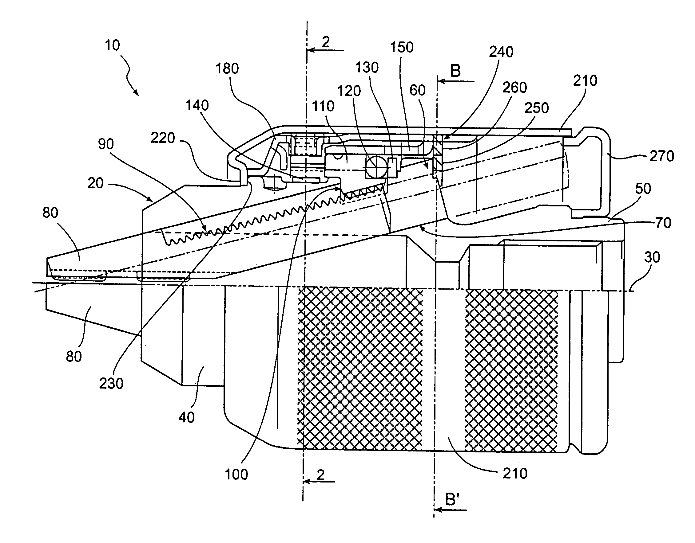
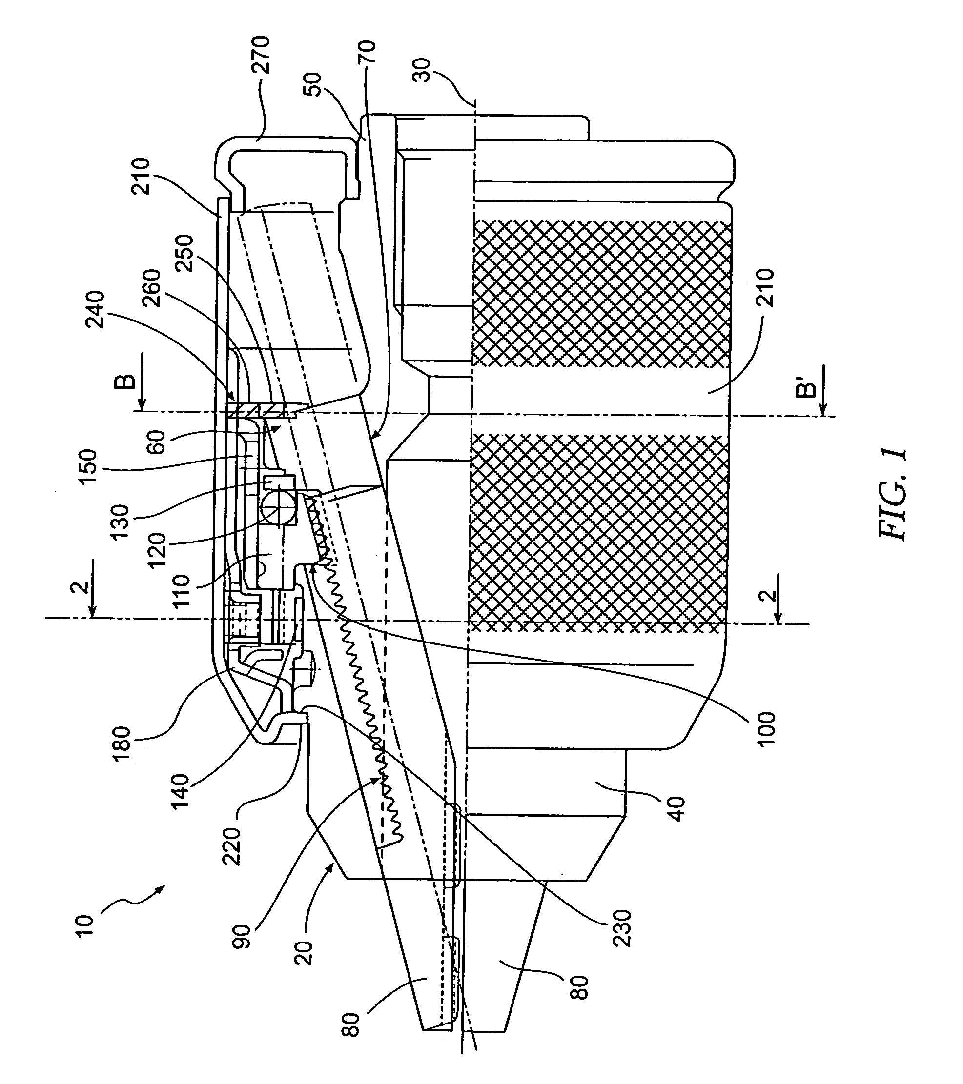
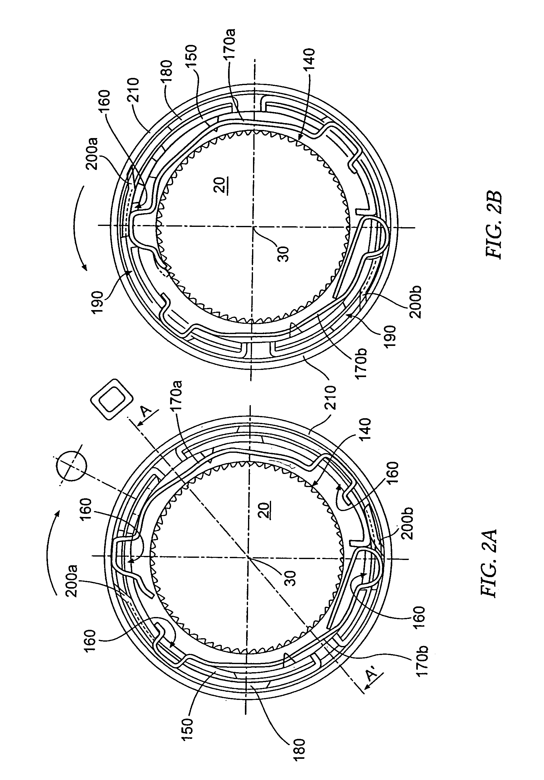
[0018]FIG. 1 illustrates a keyless chuck according to one embodiment of the present invention, the chuck being indicated generally by the numeral 10, configured to be used with a drill or other suitable tool as will be appreciated by one skilled in the art. FIGS. 2A, 2B, and 3 further illustrate various sections and views of the chuck 10. Such a chuck 10 includes a generally cylindrical body 20 defining an axis 30 and having a forward portion 40 and a rearward portion 50 with respect to the axis 30. In one embodim...


PUM


Abstract

A keyless chuck is provided, comprising a generally cylindrical body having a forward and rearward portion with respect to an axis, the forward portion including a radially outwardly projecting portion of the body. The body further includes a plurality of guides extending obliquely to the axis and converging toward the forward section, and a groove extending around the body. Each of a plurality of jaws is slidably disposed within a respective guide and includes a thread section along an outer surface thereof. A jaw-engaging mechanism is configured to operably engage the groove so as to be rotatable around the body, and includes a thread section configured to complementarily engage the thread sections of the jaws. A sleeve extends over the jaw-engaging mechanism. A retaining member is disposed substantially within the sleeve, and is operably engaged with and extends between the body and the sleeve, rearwardly of the radially outwardly projecting portion of the body. The retaining member thereby axially constrains the sleeve with respect to movement toward the forward portion of the body. An associated method is also provided.

Description

CROSS-REFERENCE TO RELATED APPLICATIONS[0001]This application is a continuation of U.S. patent application Ser. No. 10 / 421,662, filed Apr. 23, 2003 now U.S. Pat. No. 6,959,931; which is a continuation-in-part of U.S. patent application Ser. No. 09 / 983,499, filed Oct. 23, 2001 now U.S. Pat. No. 6,659,474; which claims priority from Japanese Patent Application No. 2001-260708, filed Aug. 30, 2001; each of these applications being incorporated herein by reference in their entirety.BACKGROUND OF THE INVENTION[0002]1. Field of the Invention[0003]The present invention relates to drill chucks and, more particularly, to a keyless chuck and associated method.[0004]2. Description of Related Art[0005]A standard drill chuck has a body centered on and rotatable about an axis and typically includes a plurality of angled guides extending obliquely to the axis and opening toward the forward end of the chuck. A corresponding plurality of jaws are slidably engaged with the guides, each jaw having a t...

Claims


Application Information

Patent Timeline
Patent Type & Authority Patents(United States)
IPC IPC(8): B23P11/00B23B31/12
CPCB23B31/123B23B31/1238B23B2231/38Y10S279/902Y10T29/49844Y10T29/49879Y10T29/49945Y10T279/32Y10T279/17632
Inventor SAKAMAKI, KAZUOSAKAMAKI, AKIRASATO, CHOKICHITANIGUCHI, TADASHI
Owner YUKIWA SEIKO
Features
  • R&D
  • Intellectual Property
  • Life Sciences
  • Materials
  • Tech Scout
  • Unparalleled Data Quality
  • Higher Quality Content
  • 60% Fewer Hallucinations
Learn More