Fastener having supplemental support and retention capabilities
What is AI technical title?
AI technical title is built by PatSnap AI team. It summarizes the technical point description of the patent document.
a technology of supplemental support and retention capability, applied in the field of fasteners, can solve the problems of affecting the sole function of the fastener, inflicting injury on innocent bystanders, and destroying property in its wak
Inactive Publication Date: 2007-02-27
NELSON CHARLES +2
View PDF27 Cites 10 Cited by
Summary
Abstract
Description
Claims
Application Information
AI Technical Summary
This helps you quickly interpret patents by identifying the three key elements:
Problems solved by technology
Method used
Benefits of technology
Problems solved by technology
However, in regions subject to windy conditions and / or earthquakes, these fasteners may fail to perform their sole function which sometimes results in unfortunate consequences.
For example, these fasteners, often times, are subject to high tensile and / or shear forces which cause the shaft to break thereby allowing the fastened material to separate during high winds or wind gusts, or during vibrations from an earthquake.
When this occurs, the unfastened materials depart from their fastened or intended location and may inflict injury to innocent bystanders or may damage property in its wake.
However, in these fasteners, the reduction in weight has caused a corresponding reduction in strength and / or the ability to withstand other tensile or shear forces caused by the stresses to which the assembly may be subjected.
Typically, a molded, non-metallic fastener having an external coating of metal provides a lightweight fastener, but is unlikely to have the desired strength to withstand severe tensile and / or shear forces without a significant increase in size.
Also, metal coated non-metallic fasteners typically cannot be used in conjunction with metallic structures since the relatively thin metallic coating can be quickly destroyed or worn away by the metallic structures, thereby permitting the assembled structures to act against the more fragile non-metallic core material.
Thus, under the high stress conditions in which these fasteners may be used, failures can occur resulting in cutting through or shearing of the non-metallic core.
Method used
Image
Click on the blue label to locate the original text in one second.
Reading with bidirectional positioning of images and text.
Examples
Embodiment Construction
[0035]It is to be understood that the figures and descriptions of the present invention may have been simplified to illustrate elements that are relevant for a clear understanding of the present invention, while eliminating, for purposes of clarity, other elements found in a typical fastener. Those of ordinary skill in the art will recognize that other elements may be desirable and / or required in order to implement the present invention. However, because such elements are well known in the art, and because they do not facilitate a better understanding of the present invention, a discussion of such elements is not provided herein. It is also to be understood that the drawings included herewith only provide diagrammatic representations of the presently preferred structures of the present invention and that structures falling within the scope of the present invention may include structures different than those shown in the drawings. Reference will now be made to the drawings wherein li...
PUM
Abstract
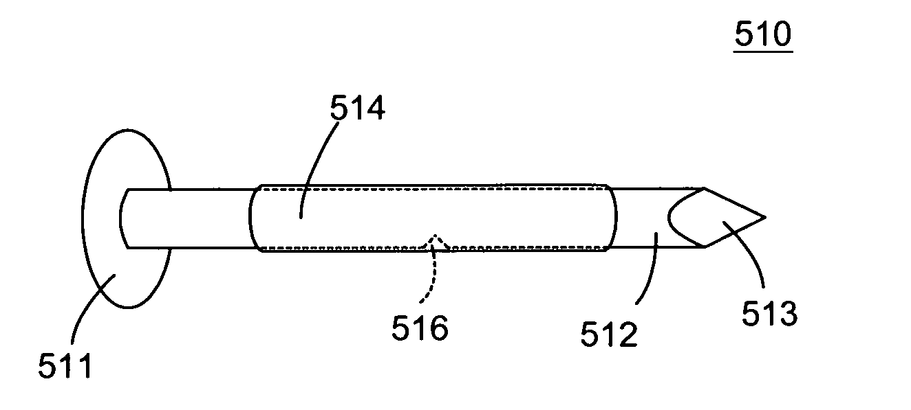
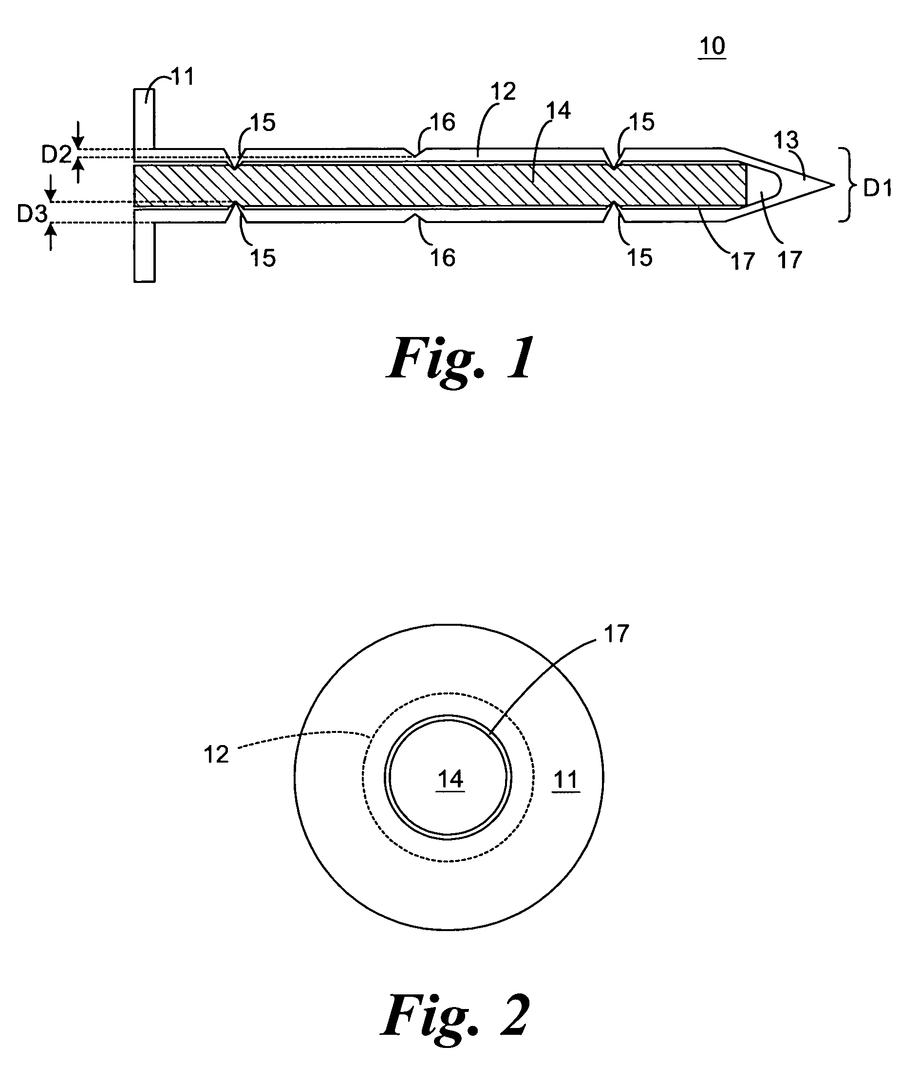
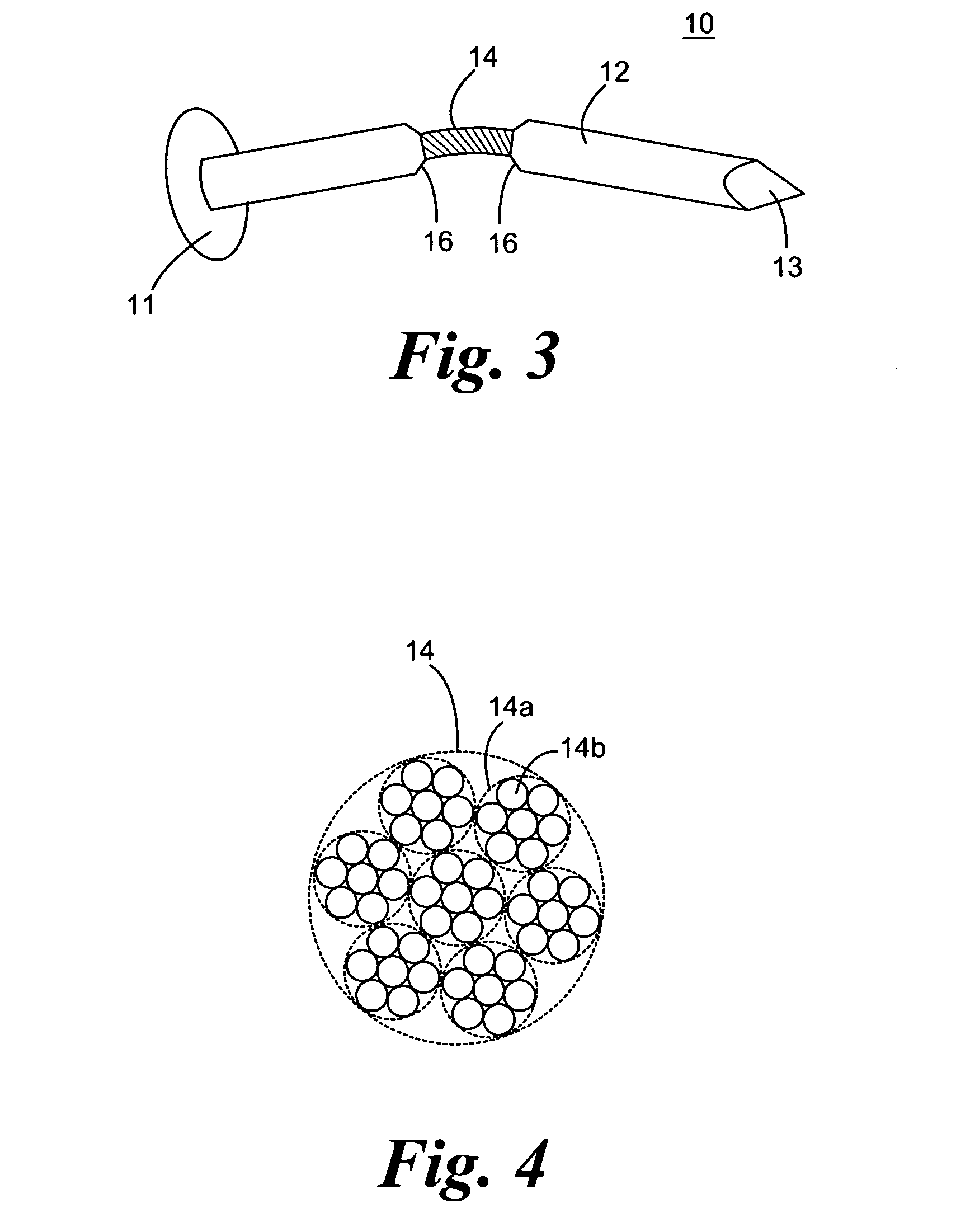
A fastener, such as a nail, screw, etc., which possesses supplemental support and / or retention capability is provided. The fastener includes an elongated auxiliary member secured interiorly to, exteriorly to, or along the shaft of the fastener. The auxiliary member is secured to the shaft at two or more portions of the shaft. The auxiliary member provides the shaft with additional support strength and / or enables fastened materials to be retained upon breakage or shearing of the shaft as a result of, for example, heavy tensile or shearing loads. To facilitate breakage or shearing of the shaft, the shaft may be provided with a deformation, such as a notch or reduced circumference, at one or more desired locations such that the shaft breaks or shears at the deformation(s), thereby allowing the auxiliary member to function as the sole member which retains the fastened materials. The auxiliary member may be sufficiently flexible and pliable such that, upon breakage or shearing of the shaft, retention of the materials is maintained but in a less stressed form.
Description
[0001]This application is a divisional of U.S. patent application Ser. No. 10 / 134,866, filed Apr. 29, 2002, issuing on Jun. 21, 2005 as U.S. Pat. No. 6,908,275.FIELD OF THE INVENTION[0002]The present invention relates generally to the field of fasteners. In particular, the present invention relates to fasteners which possess supplemental support and retention capabilities. More specifically, the present invention relates to fasteners which possess supplemental support, and which possess retention capabilities upon breakage of the fastener shaft, by utilizing an elongated auxiliary member secured interiorly or exteriorly to the shaft, or along the shaft.BACKGROUND OF THE INVENTION[0003]In various instances, a fastener, e.g. a nail or screw, has been used to hold a material in place, such as house siding, shingles, sheathing, panels, structural members, etc., or to fasten studs, joists, beams, etc. In most cases, keeping materials fastened together is the sole goal and purpose of the ...
Claims
Application Information
Patent Timeline
Application Date:The date an application was filed.
Publication Date:The date a patent or application was officially published.
First Publication Date:The earliest publication date of a patent with the same application number.
Issue Date:Publication date of the patent grant document.
PCT Entry Date:The Entry date of PCT National Phase.
Estimated Expiry Date:The statutory expiry date of a patent right according to the Patent Law, and it is the longest term of protection that the patent right can achieve without the termination of the patent right due to other reasons(Term extension factor has been taken into account ).
Invalid Date:Actual expiry date is based on effective date or publication date of legal transaction data of invalid patent.
Patent Type & AuthorityPatents(United States)
IPC IPC(8): F16B15/00F16B35/04
CPCF16B15/00F16B35/041Y10S411/901
InventorNELSON, CHARLESESSERMAN, MATTHEW J.SCHNEIDER, JAMES E.

