Check patentability & draft patents in minutes with Patsnap Eureka AI!

Drilling device and method for producing undercut holes

a drilling device and drilling method technology, applied in directional drilling, manufacturing tools, borehole/well accessories, etc., can solve the problems of reducing load-bearing capacity, hand-guided versions, and not giving satisfactory results

Inactive Publication Date: 2007-03-13
GEUVERS PAUL +1
View PDF49 Cites 5 Cited by
  • Summary
  • Abstract
  • Description
  • Claims
  • Application Information

AI Technical Summary

Problems solved by technology

With cracked concrete, it is necessary to prevent the dowel connection from yielding or subsiding owing to the cracking, which would reduce the load-bearing capacity.
The difficulty usually is to remove the drilling dust on site and ensure unrestricted use under the rough conditions found at building sites.
These methods and devices, hitherto in hand-guided versions, have not given satisfactory results with regard to the requirements of “widening” and “undercutting”, and therefore have not been commercially successful.

Method used


Image

  • Drilling device and method for producing undercut holes
  • Drilling device and method for producing undercut holes
  • Drilling device and method for producing undercut holes

Examples


second embodiment

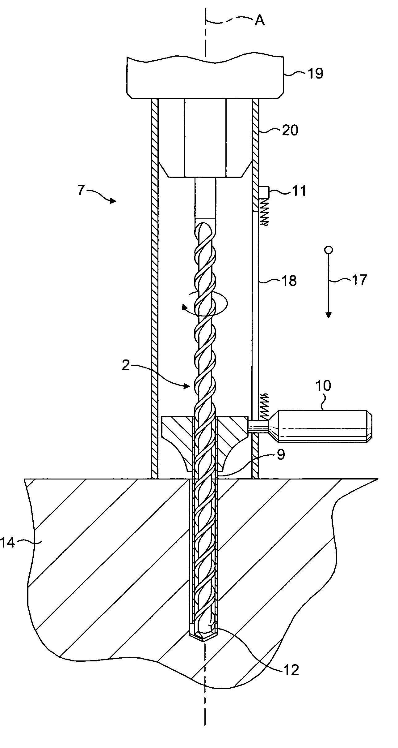
[0039]FIG. 8 shows the drilling device 7. For ease of reference, like reference numerals are used to indicate similar or identical parts. In this embodiment, the outer tube 20 is replaced by a generally L-shaped support 20 that cooperates with an adjustable depth stop 8. The handle 10 connects with the guide tube 9 via a slot 31 in a limb of the support 20 that extends parallel to the drilling tool 2 and sleeve 9. The slot allows the handle 10 to move axially, but substantially prevents rotational movement thereof. Accordingly, the operator can move the guide tube 9 axially on the drill shaft, but rotation of the guide tube 9 is substantially prevented.

[0040]A marking device 30 is carried by the handle 10 and is arranged to mark the part 14 being drilled at a position 32 when the undercut 12 is made. The marking device 30 will only mark the part 14 when the guide tube 9 is fully inserted in the hole to produce a fully formed undercut 12. The distance moved by the handle 10 to fully ...

third embodiment

[0049]FIG. 13 shows the drilling device 7 in which, in contrast to the embodiment shown in FIGS. 3 and 4, the depth stop system is provided inside telescopic outer tubes 42 and 43, which replace the outer tube 20.

[0050]FIG. 13 shows the third embodiment in position at the commencement of a drilling operation. For ease of reference, like or similar parts will be referenced by the same reference numerals as in the previously described embodiments. In this embodiment the previously described outer tube 20 is replaced by a telescopic tube arrangement comprising at least two tubes 42, 43. The upper telescopic tube 42 is fastened to the hammer drill 19 and the lower telescopic tube 43 is connected to the tube 42. The lower telescopic tube 43 is secured to the upper telescopic tube 42 by means of a screw 46 that penetrates an elongate slot 45 provided in the upper telescopic tube. This slot 45 is sufficiently long to permit the tubes 42, 43 to telescope as the drilling tool 2 moves to a pr...


PUM

PropertyMeasurementUnit
drilling depthaaaaaaaaaa
movementaaaaaaaaaa
lengthaaaaaaaaaa

Abstract

A drilling device for producing undercut holes. The drilling device includes a drilling tool having an axis of rotation and a cutting portion arranged such that the cutting portion drills a hole with a longitudinal axis that is radially offset with respect to said axis of rotation and a centering device operable to apply a lateral force to said drilling tool for moving said axis of rotation towards said longitudinal axis to cause said cutting portion to form an undercut in a said hole.

Description

CROSS REFERENCE TO CO-PENDING APPLICATIONS[0001]This invention claims the benefit of German Patent Application No. 103 11 079.8 filed on Mar. 13, 2003, which is hereby incorporated by reference.FIELD OF THE INVENTION[0002]The invention relates to a drilling device and method of working concrete, brickwork, stone or the like by means of a drilling operation to produce undercut holes.BACKGROUND OF THE INVENTION[0003]The production of cylindrical drill holes in materials such as concrete, brickwork, stone and the like using various techniques generally referred to as “drilling” is common. Often during above-ground, below-ground and street construction, for example, accurately positioned drill holes are needed, for example, for inserting fastening elements. Provided the holes are simple “passage holes”, the process is relatively simple, since there are no special requirements on the shape or geometry of the hole, apart from the nominal diameter. Dowel connections on the other hand impos...

Claims


Application Information

Patent Timeline
Patent Type & Authority Patents(United States)
IPC IPC(8): E21B7/28B23B41/00B23B47/00E21B10/00B23B49/02B23B51/00
CPCB23B49/02B23B51/0036Y10T408/93Y10T82/12
Inventor GEUVERS, PAULGAUDRON, PAUL
Owner GEUVERS PAUL
Features
  • R&D
  • Intellectual Property
  • Life Sciences
  • Materials
  • Tech Scout
  • Unparalleled Data Quality
  • Higher Quality Content
  • 60% Fewer Hallucinations
Learn More