Electric motor pole position sensing method, pole position sensing apparatus, and electric motor control apparatus using the same

Inactive Publication Date: 2007-03-13
YASKAWA DENKI KK
View PDF24 Cites 30 Cited by
  • Summary
  • Abstract
  • Description
  • Claims
  • Application Information

AI Technical Summary

Benefits of technology

[0009]It is an object of the invention to provide a method of detecting a magnetic pole position of a motor and an apparatus for detecting a magnetic pole position in which, although high-frequency currents of carrier frequency components or the li

Problems solved by technology

However, a method, which estimates the speed and position of a rotor on the basis of an induced voltage of a motor, operates with sufficient accuracy in a high speed region, but cannot perform correct estimation at a very low speed from which little information of the induced voltage is obtained.
However, a special signal generator is necessary in order to inject such a sens

Method used


Image

  • Electric motor pole position sensing method, pole position sensing apparatus, and electric motor control apparatus using the same
  • Electric motor pole position sensing method, pole position sensing apparatus, and electric motor control apparatus using the same
  • Electric motor pole position sensing method, pole position sensing apparatus, and electric motor control apparatus using the same

Examples


Example

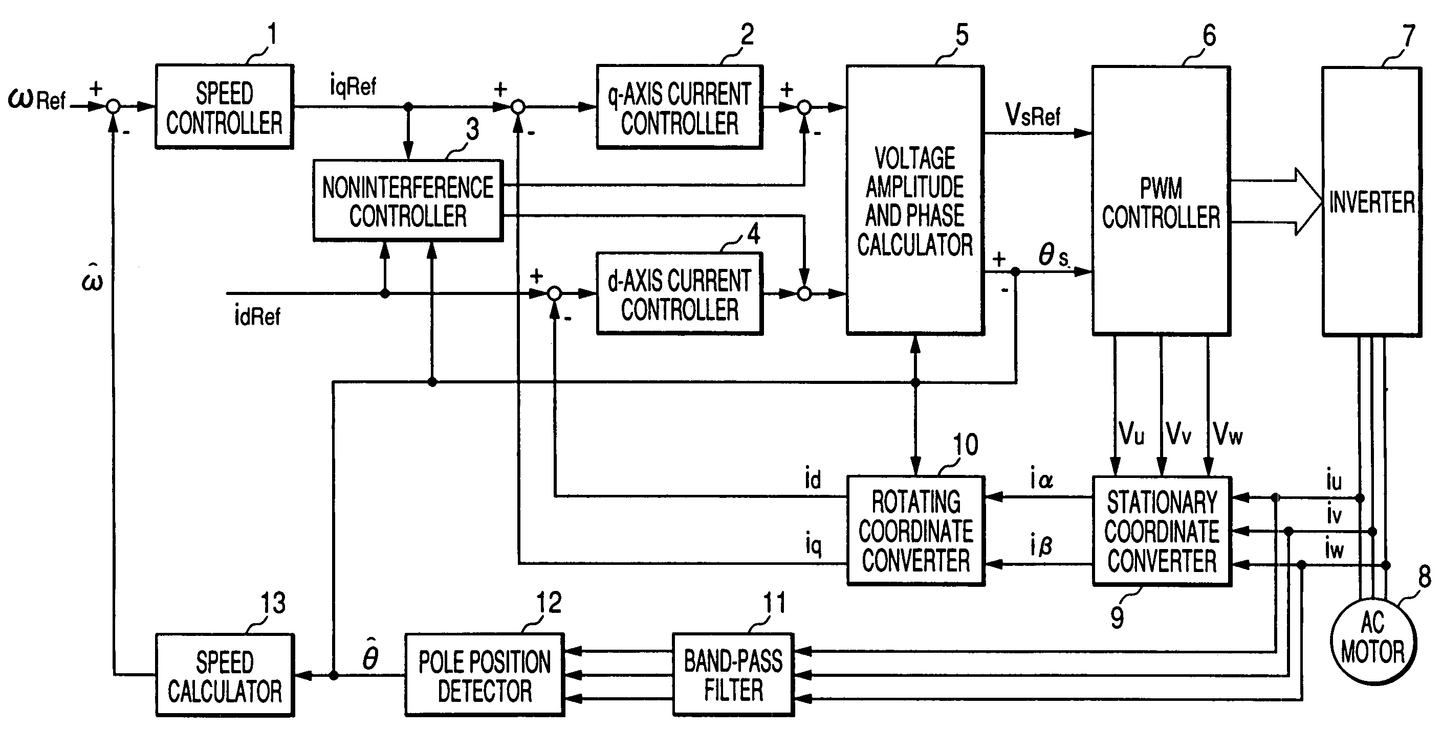
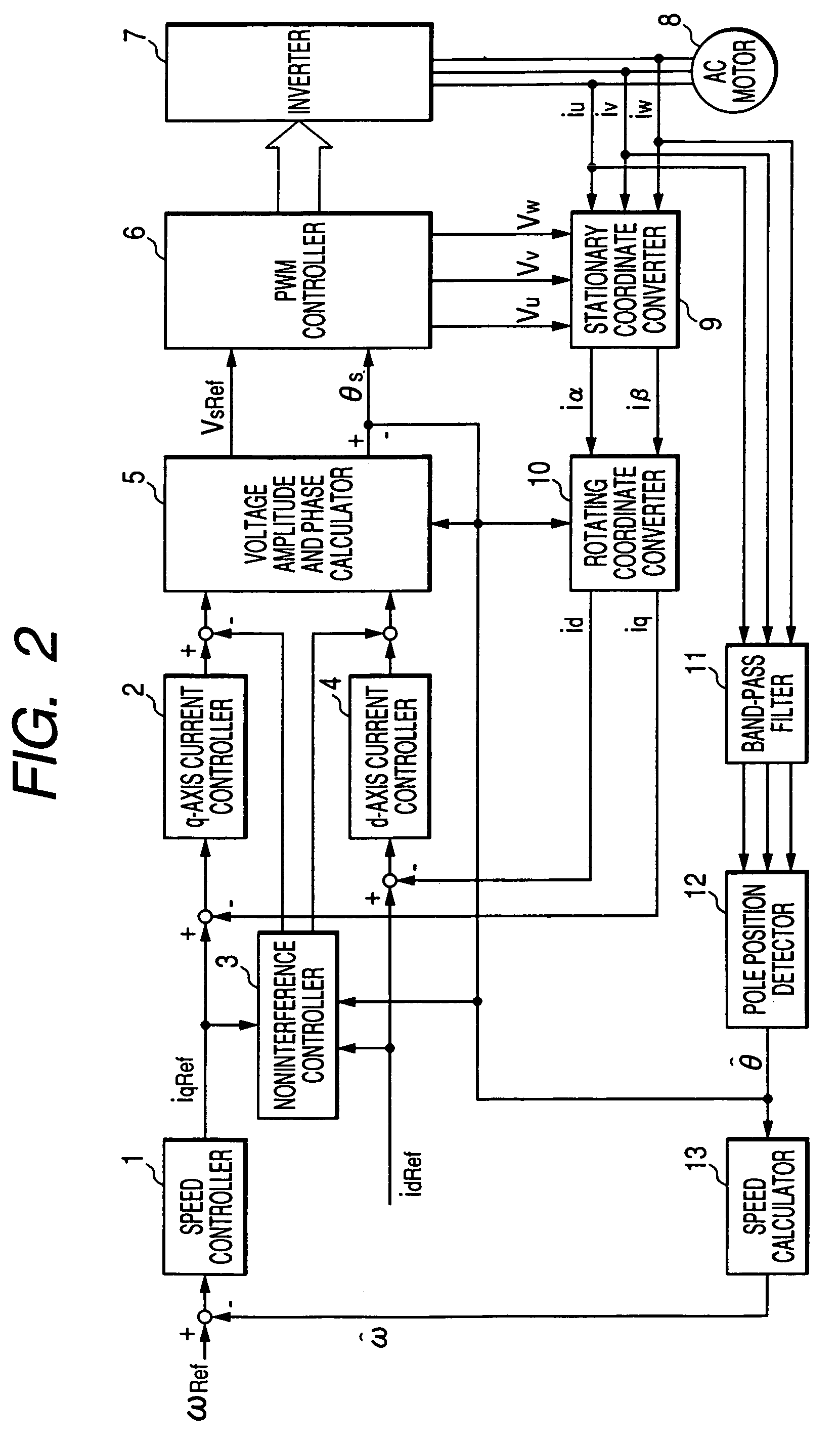
[0030]First, the invention is based on a method of detecting a magnetic pole position by using a current of a carrier frequency component, and the basic principle of the magnetic pole position detection will be described. In a vector controlling apparatus for a synchronous motor which is driven by a voltage source PWM inverter, an arbitrary phase difference is produced between PWM carrier signals of respective two phases such as UV, VW, or WU of three or U-, V-, and W-phases, thereby generating high-frequency voltages and high-frequency currents that are different from a driving frequency. Namely, the frequency band of generated high-frequency components can be adjusted to a frequency different from the driving frequency by arbitrarily giving the frequencies of the PWM carriers and the phase difference of the carriers. When the phase difference is 120 deg., for example, voltage and current components the frequencies of which are equal to the carrier frequency largely appear. In this...


PUM


Abstract

It is an object of the invention to provide a method which can detect a magnetic pole position easily and surely by using high-frequency currents such as harmonics of an inverter output and carrier frequency components. The invention provides a method of detecting a magnetic pole position of a motor and an apparatus for detecting a magnetic pole position in which, although high-frequency currents of carrier frequency components or the like are used, a special current detecting circuit is not required, and synchronization between the current detection timing and the position calculation can be easily attained, and also to provide an apparatus for controlling a motor using the same.

Description

CROSS-REFERENCE TO RELATED APPLICATIONS[0001]This application is based on a Japanese patent application (JP-A-2001-238060) filed Aug. 6, 2001, and the contents of the patent application are incorporated herein by reference.[0002]1. Field of the Invention[0003]The present invention relates to an apparatus for controlling a motor which accurately estimates a magnetic pole position at a very low speed including zero speed, and which controls the torque and the speed on the basis of the estimated magnetic pole position.[0004]2. Description of the Related Art[0005]As a conventional method of estimating a magnetic pole position, widely used is a method in which an induced voltage that is proportional to a motor speed is calculated from a motor input voltage and a current, such as that reported in “Adaptive Current Control Method for Brushless DC motor with Function of Parameter Identification” IEEJ Transactions on Industry Applications, Vol. 108 No. 12, 1988. Also known is “Zero Speed Tor...

Claims


Application Information

Patent Timeline
IPC IPC(8): H02K21/00H02P3/08H02P6/16H02P6/06H02P6/08H02P6/17H02P6/28H02P21/00H02P21/18H02P21/22H02P21/24H02P23/16H02P23/18H02P27/04H02P27/08
CPCH02P6/185H02P21/18
Inventor WOGARI, MENGESHA MAMOIDE, KOZOSAWAMURA, MITUJIRO
Owner YASKAWA DENKI KK
Why Eureka
Try Eureka