
Device for locking the legs of a passenger in a seat

a technology for passenger legs and seats, applied in seating furniture, amusements, locomotives, etc., can solve problems such as bulky devices

Inactive Publication Date: 2007-04-17
BOLLIGER & MABILLARD INGS CONSEILS SA
View PDF14 Cites 35 Cited by
  • Summary
  • Abstract
  • Description
  • Claims
  • Application Information

AI Technical Summary

Benefits of technology

"The invention is a device for locking the legs of a passenger in a seat, specifically for amusement parks. It consists of two flaps that move at the end of the seat's support. The device can be added to existing seats for better safety and security."

Problems solved by technology

Amongst other drawbacks, such a device is bulky since it requires an extension of the seat support downwards in order to serve as a support for tilting.

Method used


Image

  • Device for locking the legs of a passenger in a seat
  • Device for locking the legs of a passenger in a seat
  • Device for locking the legs of a passenger in a seat

Examples


Embodiment Construction

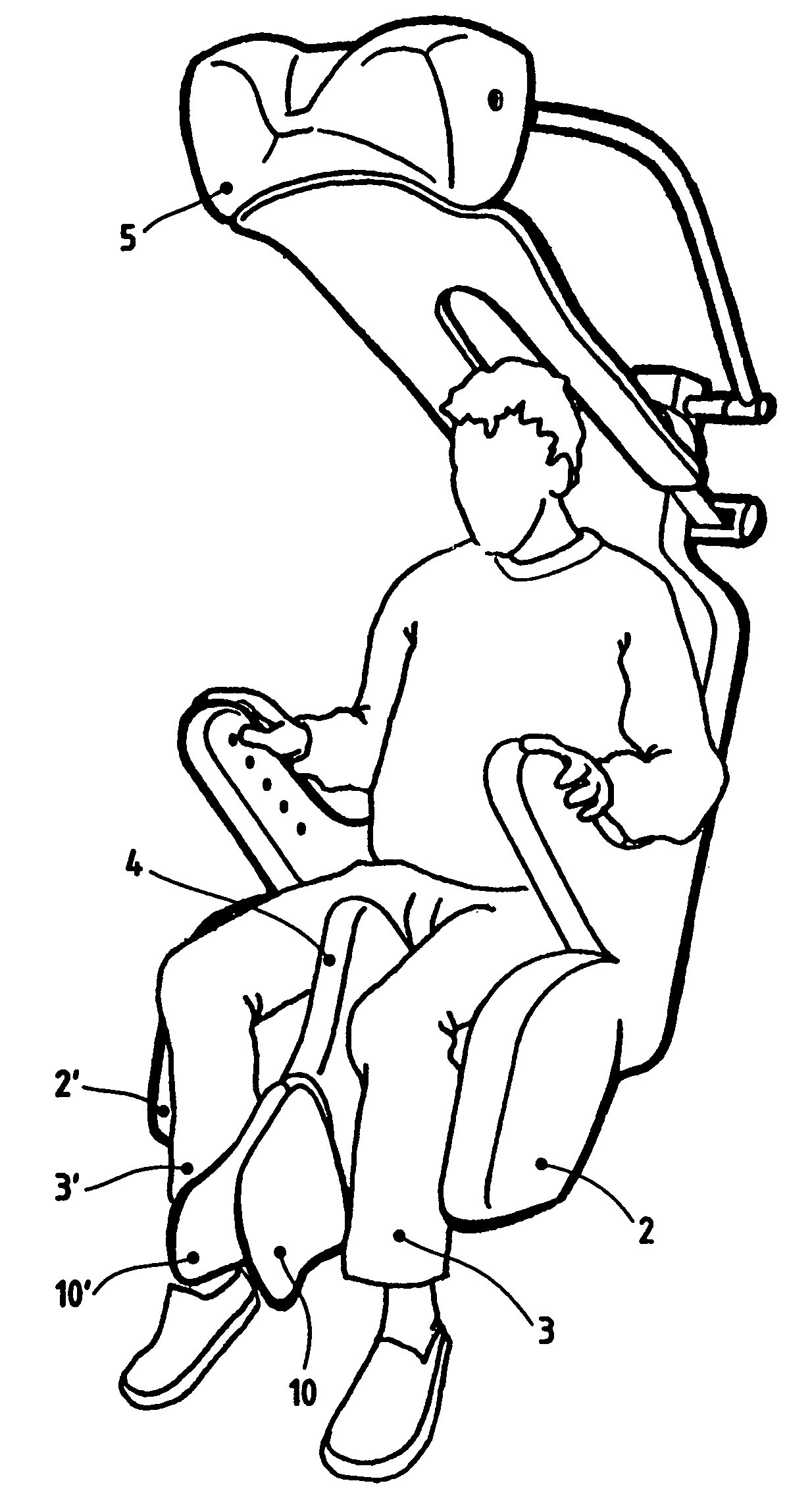
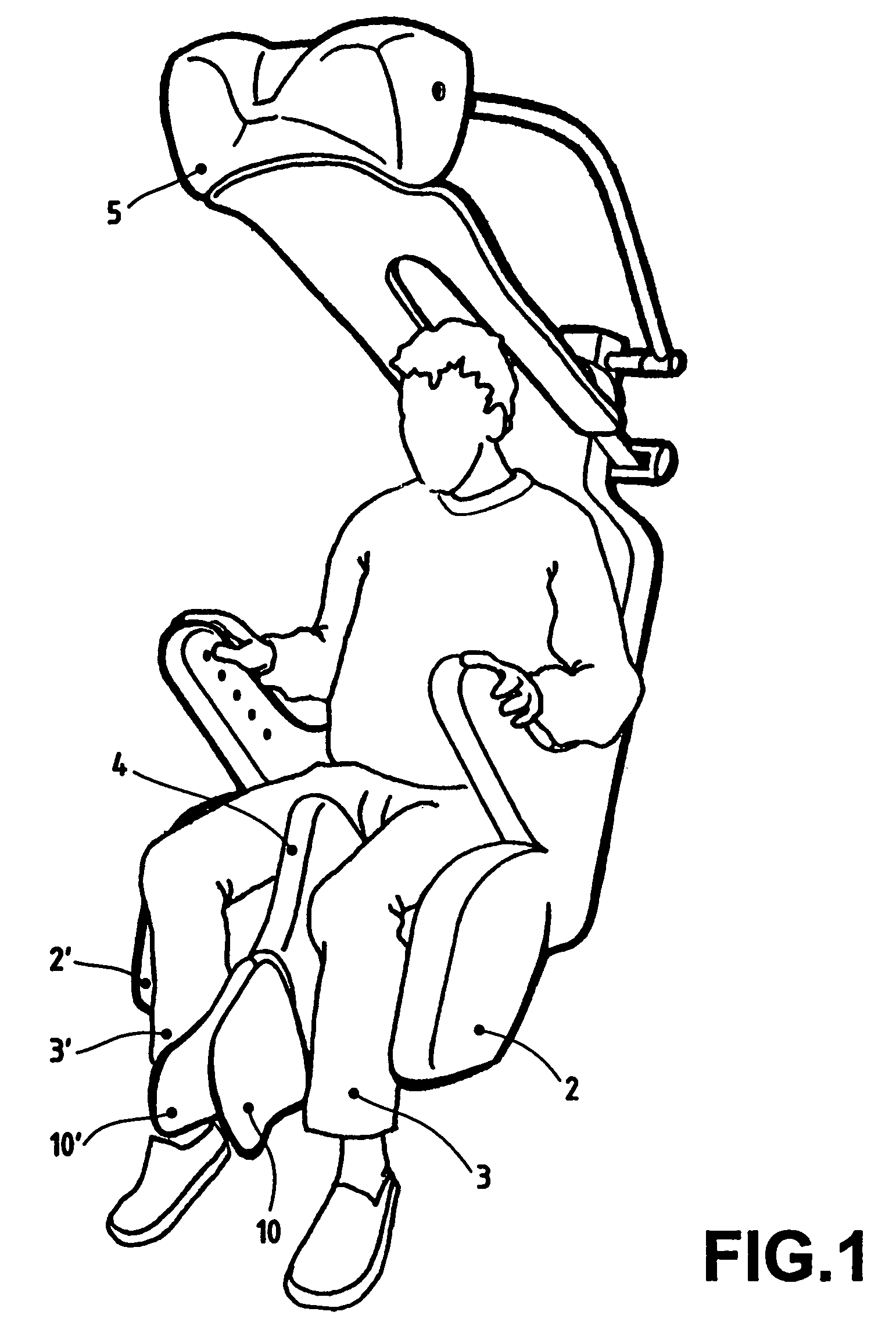
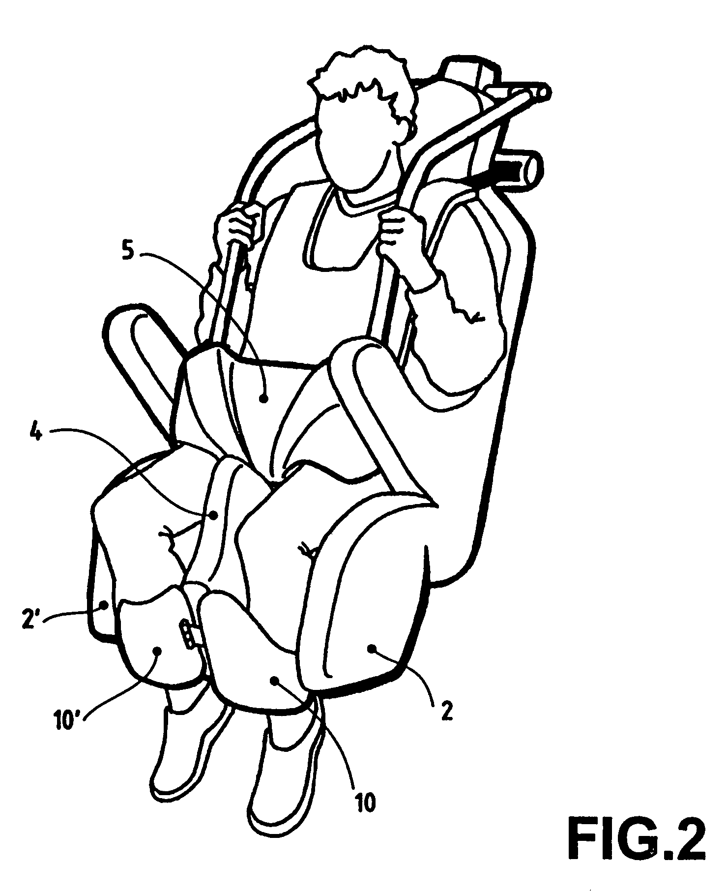
[0026]FIGS. 1 and 2 depict a seat having a device for locking the legs of a passenger according to the invention. The seat comprises a base constituting the squab part proper of the seat and having a central protrusion 4 in the shape of a camel's hump, arranged so as to cooperate with the cushion 5 of a harness and lateral parts 2, 2′ extending below the seat and serving for the lateral holding of the legs 3, 3′ of the passenger. The locking of the legs 3, 3′ is achieved by means of two flaps 10, 10′ mounted articulated at the end of the support of the seat base. When they are in the closed position, these flaps cooperate with the base of the seat and in particular with its lateral parts 2, 2′ so as to encircle the legs 3, 3′ of the passenger seated in the seat.

[0027]A first example embodiment of the opening / closing mechanism of the device is depicted in FIGS. 3 to 6. This mechanism can be mounted for example inside a beam disposed in line with the support of the seat base, at its m...


PUM


Abstract

The device, intended in particular for a seat on an installation for amusement parks, has two flaps (10, 10′) mounted for articulation at the end of the support (6) of the base (7) of the seat.

Description

BACKGROUND OF THE INVENTION[0001]1. Field of the Invention[0002]The present invention relates to a device for locking the legs of a passenger in a seat, in particular a seat on an installation for amusement parks.[0003]2. Description of Related Art[0004]Various installations are found in amusement parks where vehicles travel in which passengers sit in order to live a novel experience and to have unusual emotions and sensations.[0005]These installations offer a very broad range of sensations ranging from a simple ride, sometimes surprising in ghost trains, to aerial acrobatic figures afforded by roller coasters.[0006]The devices for holding passengers in the seats of the vehicles travelling in these installations are adapted to the speeds and accelerations to which the passengers are subjected. Thus roller coasters are provided with retaining devices including harnesses which constitute veritable yokes which encircle the body of the passenger so as to prevent any risk of ejection of ...

Claims


Application Information

Patent Timeline
Patent Type & Authority Patents(United States)
IPC IPC(8): B60R21/00B60R21/02
CPCB60R21/02B60R2021/0097A63G7/00
Inventor BERRA, ERIC
Owner BOLLIGER & MABILLARD INGS CONSEILS SA
Learn More