Contact trip mechanism for nailer

a technology of contact trip mechanism and nailer, which is applied in the direction of nailing tools, stapling tools, multi-purpose tools, etc., can solve the problems of not providing the user with the desired degree of flexibility and freedom, and not providing the user with the most efficient and effective function

Active Publication Date: 2007-05-08
BLACK & DECKER INC
View PDF44 Cites 40 Cited by
  • Summary
  • Abstract
  • Description
  • Claims
  • Application Information

AI Technical Summary

Problems solved by technology

Often times, however, the fastening tools that are available may not provide the user with a desired degree of flexibility and freedom due to the presence of hoses and such that couple the fastening tool to a source of pneumatic power.
Similarly, many features of typical fastening tools, while adequate for their intended purpose, do not provide the user with the most efficient and effective function.

Method used


Image

  • Contact trip mechanism for nailer
  • Contact trip mechanism for nailer
  • Contact trip mechanism for nailer

Examples


Embodiment Construction

[0019]The following description of the preferred embodiments is merely exemplary in nature and is in no way intended to limit the invention, its application, or uses.

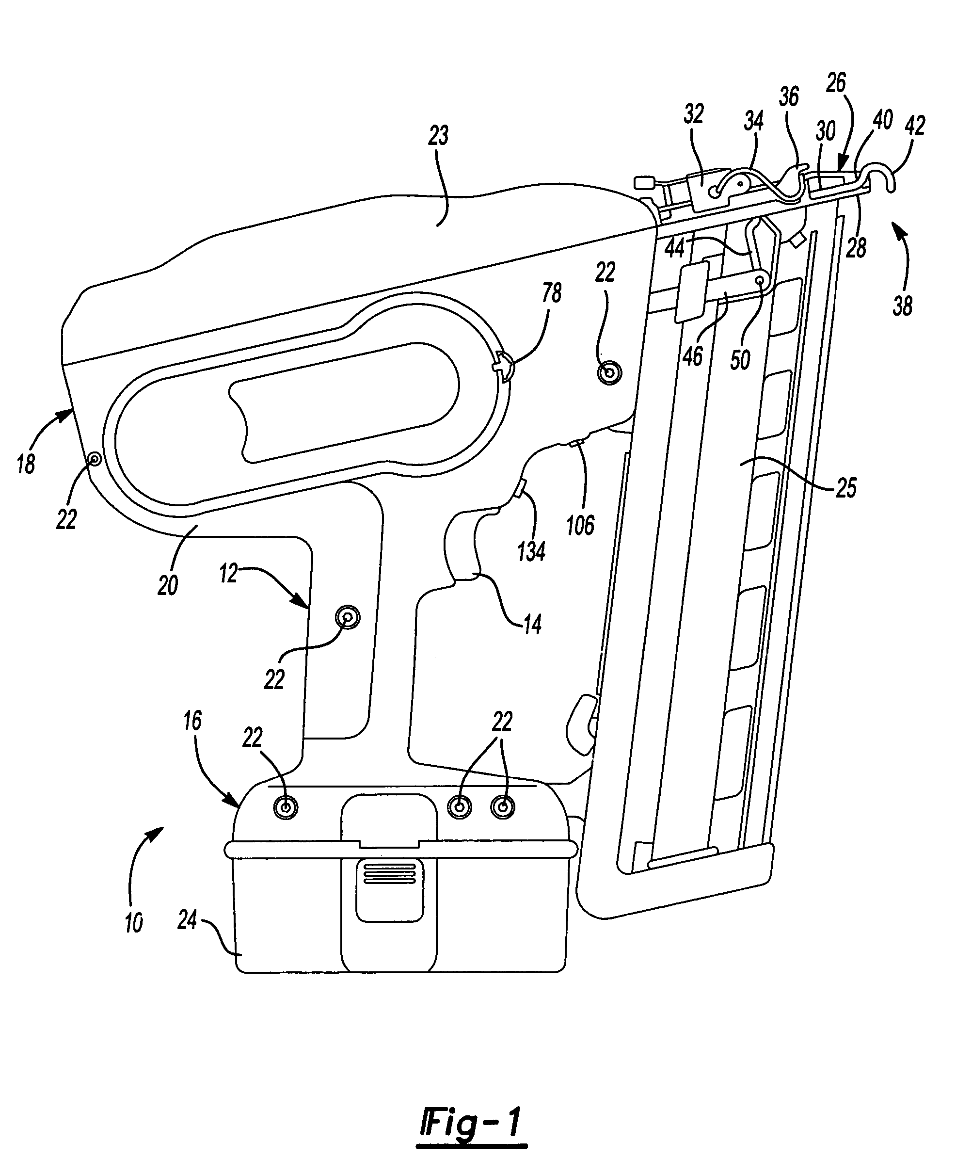
[0020]FIG. 1 is a side view of a powered fastener tool 10 according to the principles of the present invention. The tool 10 includes a main body portion 18 and a handle assembly 12, a trigger 14, and a base 16. Preferably, the handle assembly 12, base 16, and main body portion 18 are in the form of a two-piece housing 20 that is fastened together by screws 22 or the like. A backbone cover 23 is provided at the top of the main body portion 18. As shown in FIG. 1, a magazine 25 extends between the base 16 and front of the main body portion 18. A power source 24, such as a battery is mounted to the base 16 so that the tool 10 can be used as a cordless tool 10. It should be noted, however, that the tool 10 should not be limited to just the cordless configuration. More particularly, the tool 10 can be powered by an AC power ...


PUM

PropertyMeasurementUnit
angleaaaaaaaaaa
depthaaaaaaaaaa
degree of flexibilityaaaaaaaaaa

Abstract

A contact trip assembly for a power nailer, wherein a contact member includes a curved portion that loops rearwardly towards a handle of the nailer. Also provided is an adjustment assembly including an adjustment plate and a pinion gear, a trigger that is slidably engageable within a housing of the tool, a trigger lock including a ring element, an anti-discharge mechanism including a stop member, and a contact trip lock.

Description

CROSS-REFERENCE TO RELATED APPLICATIONS[0001]This application claims the benefit of U.S. Provisional Application No. 60 / 559,343, filed on Apr. 2, 2004, the disclosure of which is incorporated herein by reference.FIELD OF THE INVENTION[0002]The present invention relates to a power tool such as a power nailer. More particularly, the present invention relates to a contact trip mechanism for a power nailer.BACKGROUND OF THE INVENTION[0003]Fastening tools, such as power nailers and staplers, are relatively common place in the construction trades. Often times, however, the fastening tools that are available may not provide the user with a desired degree of flexibility and freedom due to the presence of hoses and such that couple the fastening tool to a source of pneumatic power. Similarly, many features of typical fastening tools, while adequate for their intended purpose, do not provide the user with the most efficient and effective function. Accordingly, there remains a need in the art ...

Claims


Application Information

Patent Timeline
Patent Type & Authority Patents(United States)
IPC IPC(8): B25C1/04B25C1/00B25C1/06B27F7/17
CPCB25C1/008B25C1/043B25C1/06B25C1/046Y10T16/44
Inventor SCHELL, CRAIG ABASKAR, ASHOK SAMUELGROSS, PAUL GBRADENBAUGH, CHARLES LBERRY, ROBERT ALANTOMAYKO, DAVID CXU, LI
Owner BLACK & DECKER INC
Why Eureka
Try Eureka