Adjustable shelving system

a shelving system and adjustable technology, applied in the direction of card-filing, show hangers, printing, etc., can solve the problems of costing merchant sales, difficult to rotate the product on the shelves, and the customer's difficulty in seeing the items being displayed

Inactive Publication Date: 2007-05-15
FASTENERS FOR RETAIL
View PDF90 Cites 166 Cited by
  • Summary
  • Abstract
  • Description
  • Claims
  • Application Information

AI Technical Summary

Problems solved by technology

In such stores if the shelves are not at eye level, it is difficult for the customer to see the items being displayed unless they are located adjacent the front edge of the shelf.
Such conventional shelves also make it difficult to rotate the product on the shelves, which involves moving the older stock to the front of the shelf and positioning new stock behind the older stock.
As mentioned, if the merchandise is not displayed at the front of the shelf, it may not catch the shopper's eye, which may cost the merchant sales.
Gravity feeding is somewhat unpredictable in that various materials slide easier than others because of different weights and frictional interfaces between the products and the track.
These devices are typically cumbersome, expensive and complicated due to the need to properly tension and track the conveyor belts.
Such disadvantages have to do with the fact that as the merchandise is being urged forward by the pusher, the merchandise may urge the dividers to slide laterally away from each other along the mounting member thus interfering with adjacent rows of merchandise, possibly making such merchandise more difficult to retrieve.

Method used


Image

  • Adjustable shelving system
  • Adjustable shelving system
  • Adjustable shelving system

Examples


first embodiment

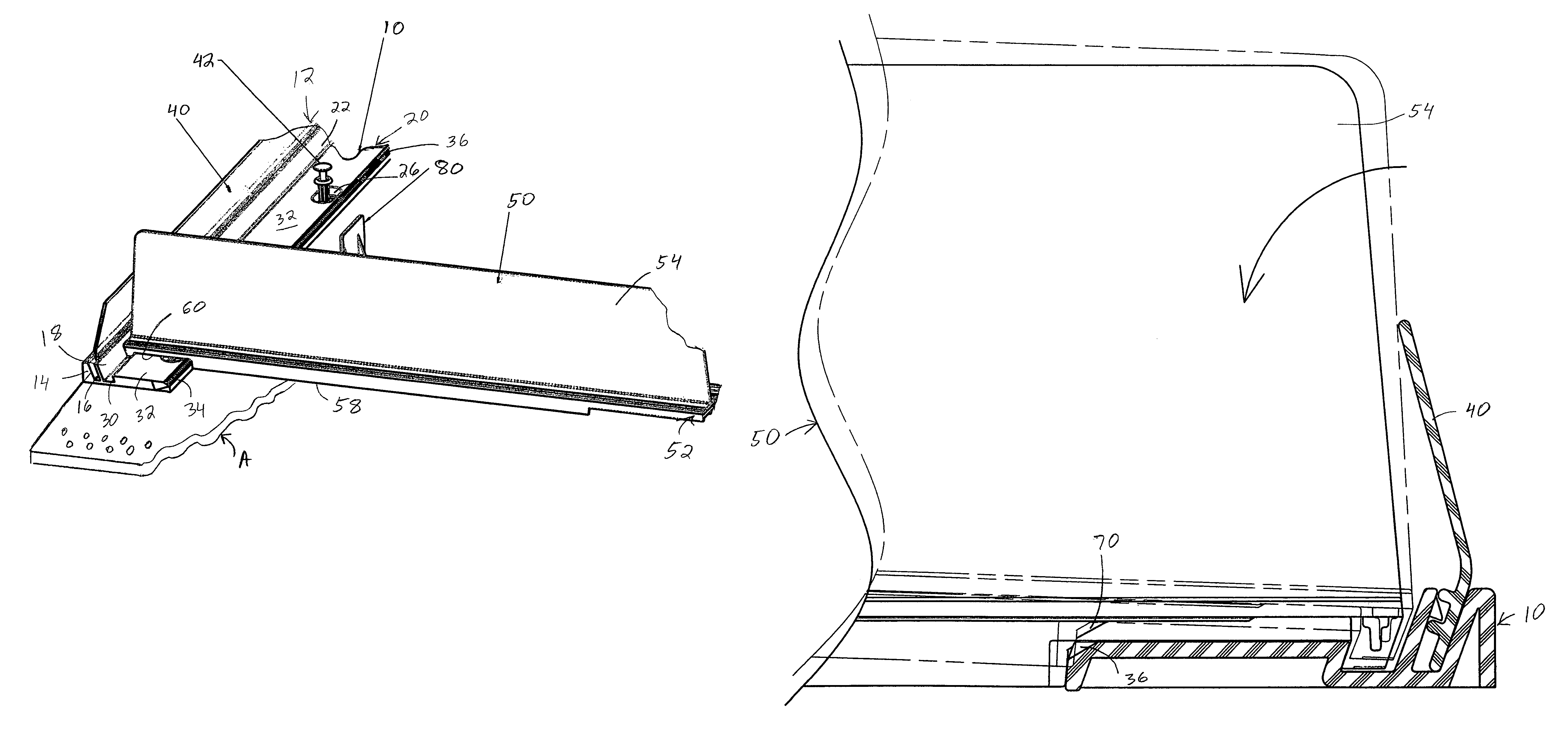
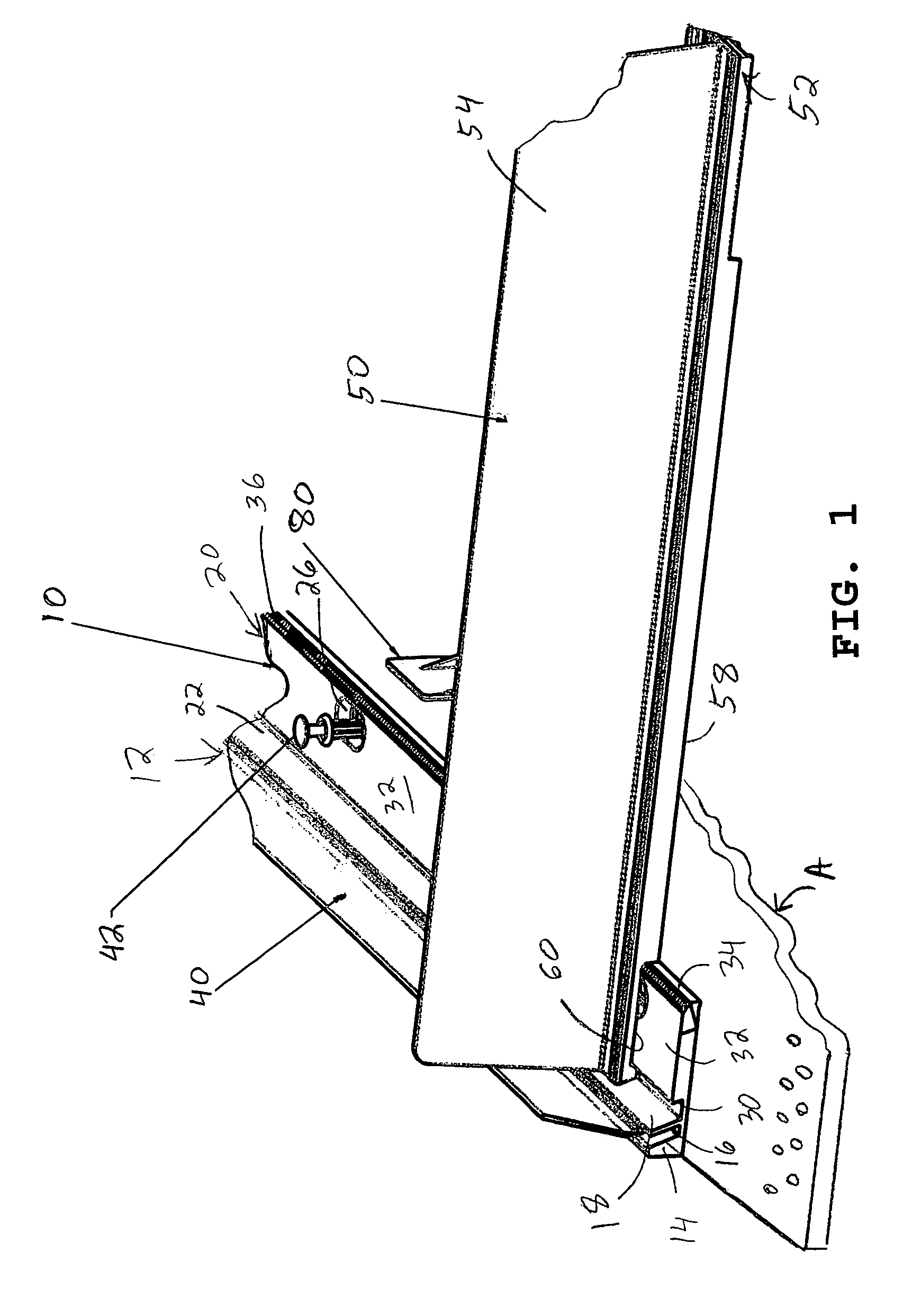
[0040]Referring now to the drawings, wherein the showings are for purposes of illustrating several preferred embodiments of the invention and not for purposes of limiting the same, FIG. 1 illustrates a shelf divider system according to the present invention. In this embodiment, a mounting member or front rail 10 includes a vertically oriented wall 12. With reference also to FIG. 7, the vertically oriented wall 12 includes a first section 14, a first groove 16 and a second section 18. Also provided on the mounting member 10 is a horizontally oriented wall 20. Disposed between the horizontally oriented wall section and the vertical wall section 12 is a second groove 22. There is a recessed portion 26 with an opening 28 located in the horizontal wall 20. The wall 20 includes a front face 30, a top face 32 and a back face 34. Defined at the intersection of the top face 32 and the back face 34 is a first row or set of teeth 36.

[0041]Mounted in the first groove 16 is a front fence 40, as ...

second embodiment

[0052]With reference now to FIG. 13, a shelf divider system according to the present invention is there illustrated. In this embodiment, a rail or mounting member includes a vertically oriented wall 192 having a first groove 194 and a horizontally oriented wall 196 as well as a second groove 198. Selectively secured to the rail is a divider 210 having a base wall 212 and a vertically oriented dividing wall 214. A transverse slot 218 extends across a bottom surface of the base. The base thus has a front edge 220 which is adapted to fit into the second groove 198 while the slot extends over the horizontal wall 196, as best shown in FIG. 14. In this embodiment, no teeth are employed. Rather, a smooth set of engaging walls is disclosed in this embodiment. Thus, the set of engaging walls can be even, free from irregularities, roughness or projections. The locking feature is achieved by suitably configuring the engaging surfaces of the slot and the mounting member horizontal wall, along t...

third embodiment

[0054]With reference now to FIG. 15, a shelf divider system according to the present invention is there illustrated. In this embodiment, a rear rail 230 is employed, instead of a front rail. The rear rail or mounting member includes a vertically oriented wall 232, a groove 234, and a horizontally oriented wall 236. The horizontally oriented wall includes a top surface 238 and a front surface 240. A first set of teeth 242 is located at the intersection of the top surface and front surface of the horizontally oriented wall 236. Selectively secured to the rear rail 230 is a divider 250. The divider includes a base wall 252 and a vertically oriented divider wall 254. A transverse groove or slot 256 is defined in the base wall 252 adjacent a rear end of the divider. The location of the slot 256 is such as to accommodate a depending rear end 258 of the divider base wall.

[0055]With reference also to FIG. 16, the divider rear end 258 is shown as being seated in the groove 234. Provided in t...


PUM


Abstract

A shelving system includes an elongated mounting member operationally securable to an associated shelf. The mounting member includes an approximately vertically oriented wall and an approximately horizontally oriented wall. A track is received on the mounting member in a non-sliding manner. The track extends transversely to a longitudinal axis of the associated shelf. An elongated rail extends longitudinally along the track. A spring urged pusher is slidably mounted in relation to the rail. A slot extends transversely along a bottom face of the track. A first smooth contact surface is located on the mounting member approximately a horizontally oriented wall. A second smooth contact surface is located on the track adjacent the slot. The second contact surface engages the first contact surface to retard a sideward sliding motion of the track in relation to the mounting member.

Description

FIELD OF THE INVENTION[0001]The present invention generally relates to adjustable shelving systems. More particularly, the present invention relates to adjustable forward feeding display shelving system for storing and displaying merchandise of a variety of shapes and sizes and urging such merchandise towards the front of a shelf. The shelving system is configured to organize merchandise on the shelf into rows.BACKGROUND OF THE INVENTION[0002]Shelving is used extensively for stocking and storing products or merchandise in a variety of stores. Most stores simply employ shelves on which merchandise is stocked. In such stores if the shelves are not at eye level, it is difficult for the customer to see the items being displayed unless they are located adjacent the front edge of the shelf. Such conventional shelves also make it difficult to rotate the product on the shelves, which involves moving the older stock to the front of the shelf and positioning new stock behind the older stock. ...

Claims


Application Information

Patent Timeline
Patent Type & Authority Patents(United States)
IPC IPC(8): A47F1/04A47F1/12A47F5/00
CPCA47F1/126A47F5/005
Inventor MUELLER, PAUL A.KUMP, DANIEL J.
Owner FASTENERS FOR RETAIL
Why Eureka
Try Eureka