Measuring torsional distortion with an easily applied clip device (saw)

a technology of torsional distortion and clip device, which is applied in the direction of measurement device, work measurement, instruments, etc., can solve the problems of limiting the possibility of retrofitting a torque measuring device to an existing shaft, requiring skilled labor and well defined manufacturing conditions, and difficult to carry out under field conditions. achieve the effect of convenient application and removal

Active Publication Date: 2007-05-29
TRANSENSE TECH
View PDF9 Cites 6 Cited by
  • Summary
  • Abstract
  • Description
  • Claims
  • Application Information

AI Technical Summary

Benefits of technology

[0012]In a particular preferred arrangement the ridges are each general V-shaped in transverse cross-section and are formed by substantially flat sides connected by a curved ridge. The curved ridge is, conveniently, a portion of the surface of a cylinder which blends into the flat sides. The grooves are also preferably V-shaped in transverse cross-section and have flat sides which either meet at a line or are connected by a curved surface of a smaller radius than that of the ridges. The included angle of the ridges is preferably less than that of the grooves. With such an arrangement, the ridges will engage the grooves along lines of contract located where the curved ridge blends into the flat sides of the ridges. Such mounting arrangement gives a particularly stable, back-lash free and well defined mounting giving a high level of mechanical stability to the arrangement and accurate interpretation of the deflection of the bridge. In the preferred embodiment of the invention the included angle of the ridges is substantially 60° and the included angle of grooves is substantially 90°.

Problems solved by technology

These techniques are well recognized as being disadvantageous because of the time and cost involved and because they limit the possibility of retrofitting a torque measuring device to an existing shaft.
Further, the mounting of the torque measuring device requires both skilled labor and well defined manufacturing conditions and is accordingly difficult to carry out under field conditions.
As a result the torque measuring device is susceptible to accidental damage during the period between mounting of the torque measuring device and the final positioning of the body whose torsional distortion is to be measured.
As a result, if the torque measuring device fails, substantial additional work will be involved in terms of removing the faulty unit before a replacement unit can be installed.

Method used


Image

  • Measuring torsional distortion with an easily applied clip device (saw)
  • Measuring torsional distortion with an easily applied clip device (saw)
  • Measuring torsional distortion with an easily applied clip device (saw)

Examples


Embodiment Construction

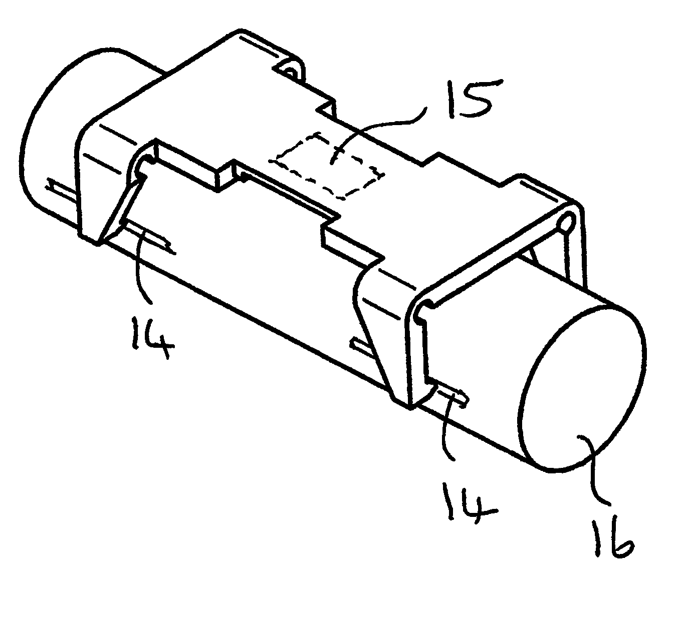
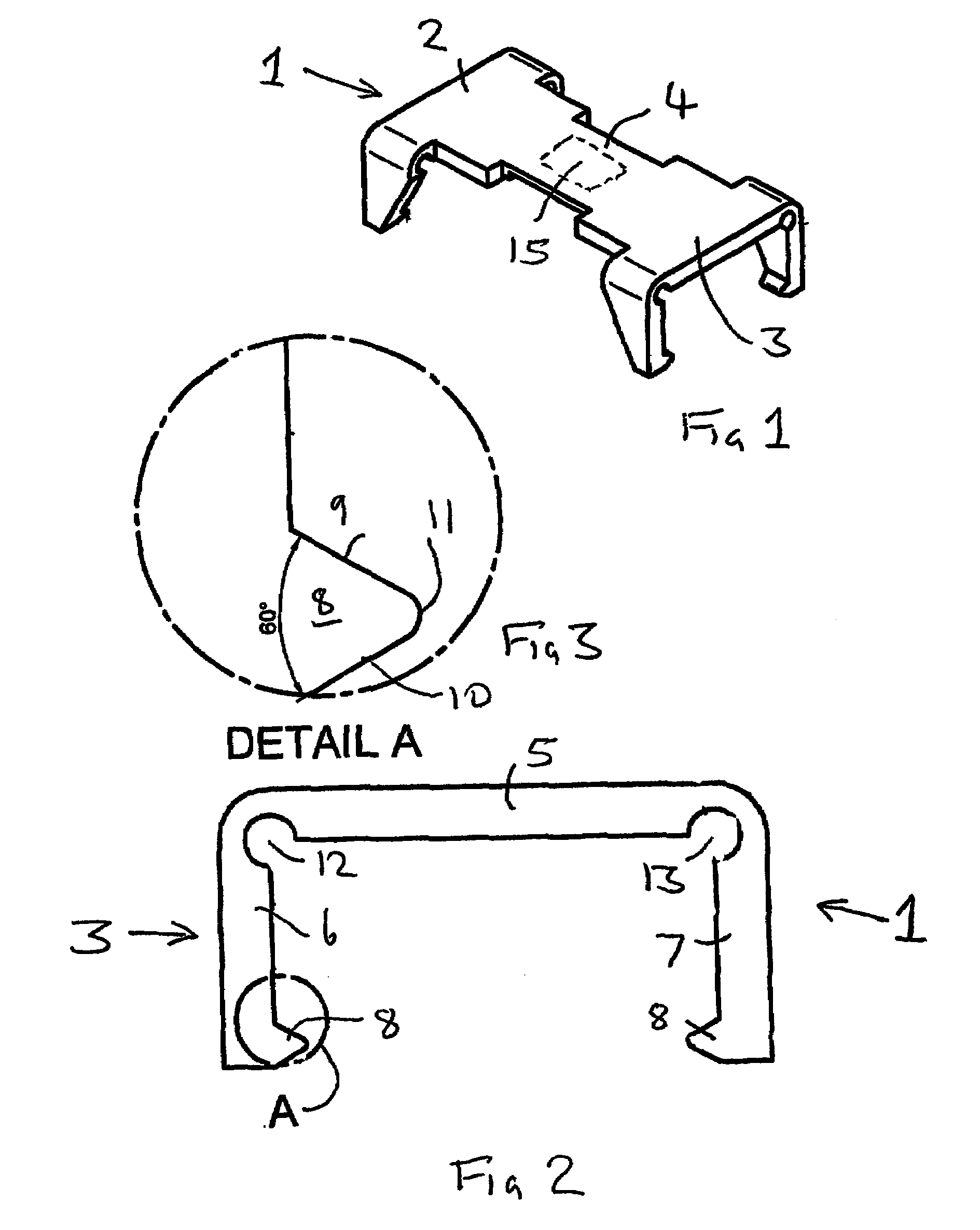
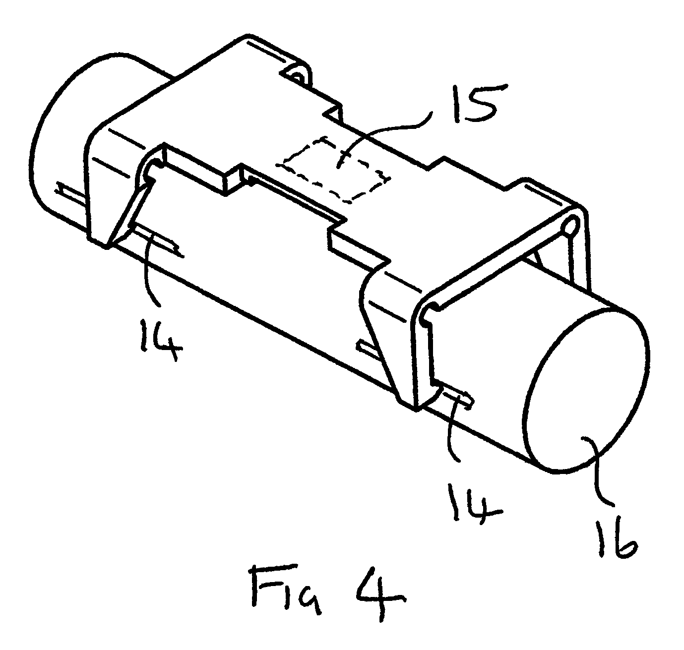
[0023]Referring firstly to FIGS. 1–3 the illustrated measuring device 1 comprises two clip portions 2,3 interconnected by a bridge portion 4. The illustrated device is an integral metal structure and may be formed by any suitable method, for example by bending a stamped or machined blank, by investment casting, or by machining from solid. The structure is designed such that the bridge 4 is relatively less stiff than the clip portions 2,3 with the result that any distortion of the device caused by mutual relative rotation of the clip portions 2,3 will cause; predominantly, deflection in the bridge 4.

[0024]Preferably, the entire structure is resilient so that it will adopt the illustrated configuration in the absence of imposed forces.

[0025]Each clip portion 2,3 comprises a central part 5 and two legs 6,7. Each leg has, at the free end thereof, a projection 8. The projections are in the form of ridges which are generally V-shaped in transverse cross-section and are made up of substant...


PUM

PropertyMeasurementUnit
included angleaaaaaaaaaa

Abstract

A device for measuring torsional distortion of a body comprises first and second clip portions each having a central part and two legs depending from the central part, each leg having adjacent the free end thereof a groove or projection for engaging a respective projection or groove (14) provided in the body (16) to mount the clip portion the body rotationally fastened therewith. A bridge interconnects the clip portion. The bridge is less stiff than the clip portions whereby relative rotational displacement of the clip portions caused by torsional distortion of the body will cause proportional deflection of the bridge. Means, for example a SAW device (15), are provided for measuring the deflection of the bridge to provide an indication of the torsional distortion which produces the deflection of the bridge. Also (20) for the interior all of a hollow body.

Description

BACKGROUND[0001]1. Technical Field[0002]This invention relates to measuring torsional distortion, and in the preferred embodiment provides a method and device for measuring the distortion in a body which is subject to applied torque. The torsional distortion measured may be used, in known manner, to determine the magnitude of the torque to which the body is subject.[0003]2. Description of Related Art[0004]It has been known for many years to measure the torque to which a body (for example a shaft) is subject by applying one or more strain gauges to the surface of the body and interrogating the output of the strain gauges to provide an indication of torque. In recent years, torque measurement techniques have been substantially improved by the introduction of Surface Acoustic Wave (“SAW”) based torque measurement devices (see for example EP-A-05 18900). Such devices have a number of well recognized advantages including high sensitivity and the ability to provide torque measurements wit...

Claims


Application Information

Patent Timeline
Patent Type & Authority Patents(United States)
IPC IPC(8): G01N3/22G01L3/04G01L3/10
CPCG01L3/10
Inventor LOHR, RAYMOND DAVIDVILE, DAVID DANIEL GEORGELEE, MARK
Owner TRANSENSE TECH
Why Eureka
Try Eureka