Device for equipping an expansion joint, in particular an expansion joint between concrete slabs

a technology of expansion joints and concrete, which is applied in the field of construction, can solve the problems of difficult alignment of individual plates along a rectilinear joint, complex systems, and difficulty in placing and keeping in pla

Inactive Publication Date: 2007-06-12
PLAKEBETON
View PDF11 Cites 29 Cited by
  • Summary
  • Abstract
  • Description
  • Claims
  • Application Information

AI Technical Summary

Benefits of technology

[0019]flat elements, which are in the same plane as said raised part and which for

Problems solved by technology

These are rather complex systems which are difficult to place and to keep in place during the casting of the slabs.
In particular, there is a difficulty in keeping the dowels parallel to each other during installation on site.
One disadvan

Method used


Image

  • Device for equipping an expansion joint, in particular an expansion joint between concrete slabs
  • Device for equipping an expansion joint, in particular an expansion joint between concrete slabs
  • Device for equipping an expansion joint, in particular an expansion joint between concrete slabs

Examples


Embodiment Construction

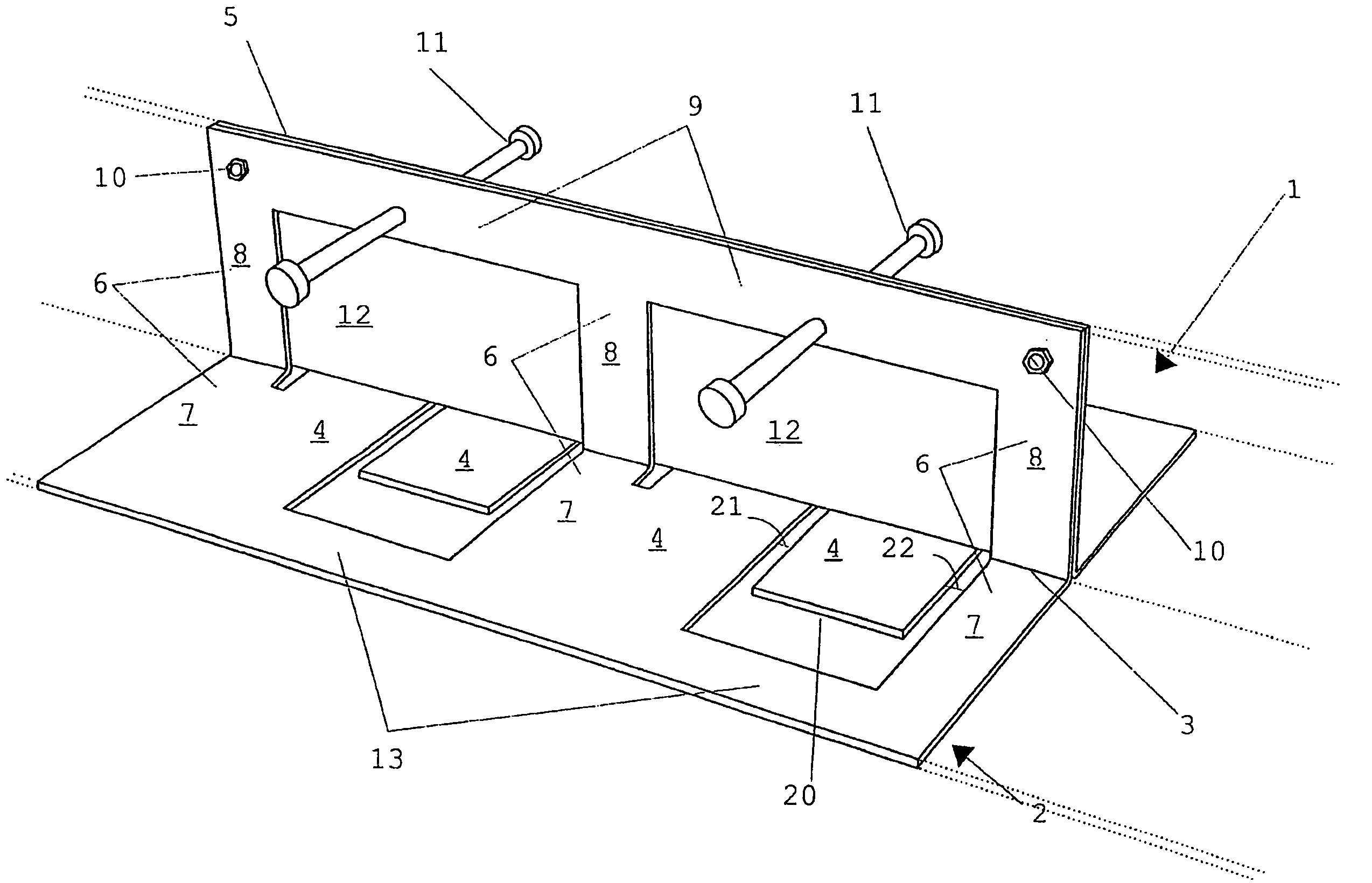
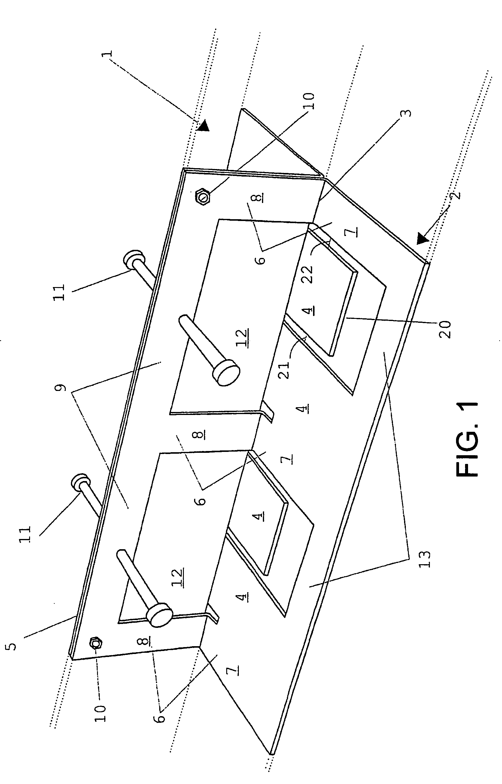
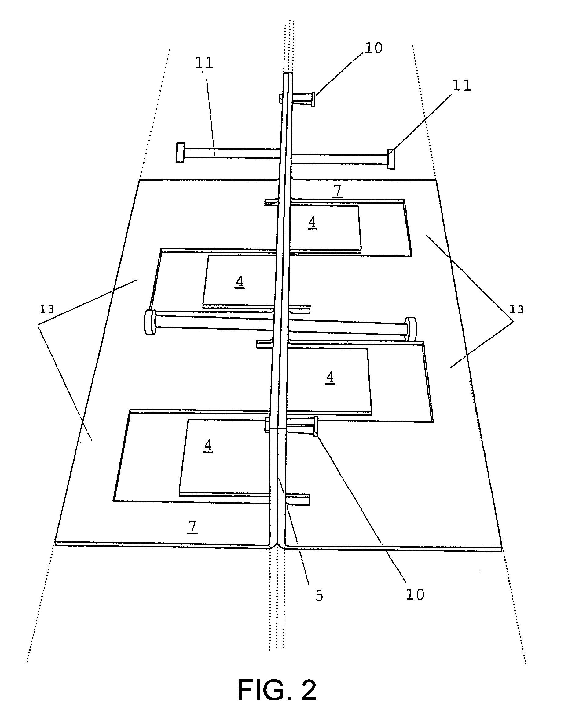
[0027]FIG. 1 shows part of a device according to the invention. As indicated by dotted lines, a complete device extends in such a way that the constituent parts repeat themselves over a longer length, more particularly the length of the complete joint which is provided. The device is constituted by two similar modules (references 1 and 2), which are constructed from two sheets of metal, preferably steel. The sheets are cut according to a predetermined pattern, then folded along a line 3 in such a way as to form meshing flat parts 4 which pass from one side of the joint to the other underneath the center plane 5. For on-site placement, the center plane 5 is provided to coincide with that of the joint between the slabs. Each module 1 or 2 derived from a cut and shaped sheet has a series of these flat plates 4, which will also be referred to as “projections”4 of each module. Between these projections 4 of each of the two modules 1 or 2, there is a series of elements 6 in the form of a ...


PUM


Abstract

A device for making a connection between concrete slabs, the device having two modules derived from sheets, each module having a number of flat elements which form projections, each module further having elements in the form of a right angle, having a flat part integral with projection, and a raised part, and longitudinal members between the raised parts, and wherein the modules are assembled in such a way that the raised parts and longitudinal members of the two modules are facing each other along the two sides of a center plane, and that the projections extend on both sides of the center plane, so as to form meshing projections which pass from one side of the joint to the other.

Description

BACKGROUND OF THE INVENTION[0001]The present invention relates to the construction sector, in particular that of slabs for industrial floors and, more particularly, concerns a device which is used for equipping expansion joints between adjacent slabs.[0002]In this description, the word “joint” is used exclusively to denote the zone or space between two adjacent slabs while, in the area of construction, this term is generally used to refer to the device itself which occupies such a zone.[0003]Devices for equipping expansion joints are known in the area of concrete structures. The effect desired from this type of device is to form a connection between adjacent slabs while at the same time allowing limited movement of one slab relative to the other in the plane of the slabs, said movement being due essentially at first to the shrinkage of concrete during setting and subsequently, after setting, to thermal expansion and contraction. The devices are supposed to ensure the transfer of loa...

Claims


Application Information

Patent Timeline
IPC IPC(8): E04F15/14E01C11/04E04B1/68E01C11/14E04B1/682
CPCE01C11/14
Inventor MICHIELS, PIERRE
Owner PLAKEBETON
Why Eureka
Try Eureka