Convertible traction shoes

a technology of traction shoes and traction cups, applied in the field of shoes, can solve the problems of not being able to meet the needs of users,

Inactive Publication Date: 2007-06-26
SELECT SOLE
View PDF22 Cites 60 Cited by
  • Summary
  • Abstract
  • Description
  • Claims
  • Application Information

AI Technical Summary

Problems solved by technology

The problem with such cleated shoes is that the cleats are not desirable on surfaces that either are impenetrable to the cleats or have surface finishes that can be damaged by the cleats (e.g., inside floors of homes, restaurants, club houses and the like).
Whereas these concepts have been in existence for years, none are considered feasible and none have found acceptability in the marketplace.

Method used


Image

  • Convertible traction shoes
  • Convertible traction shoes
  • Convertible traction shoes

Examples


Embodiment Construction

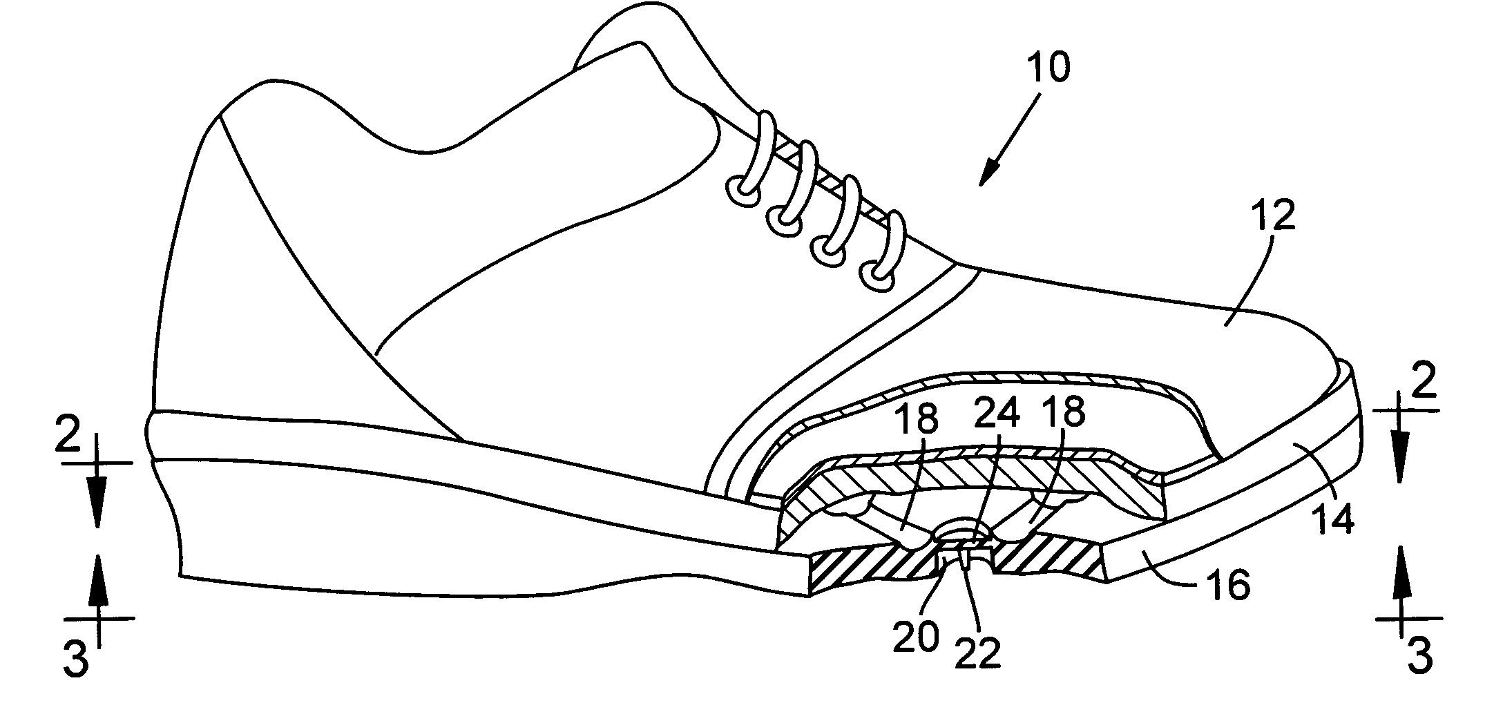
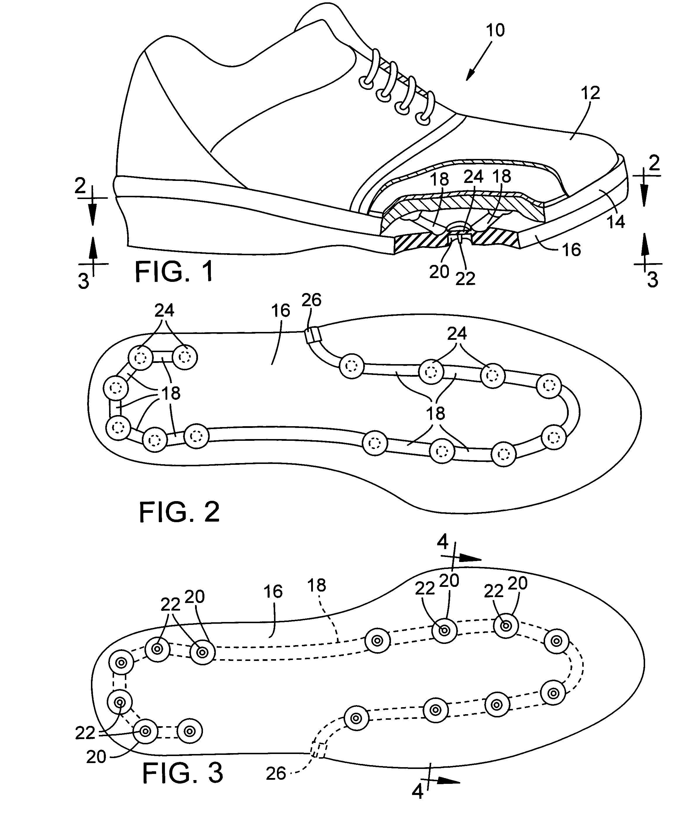
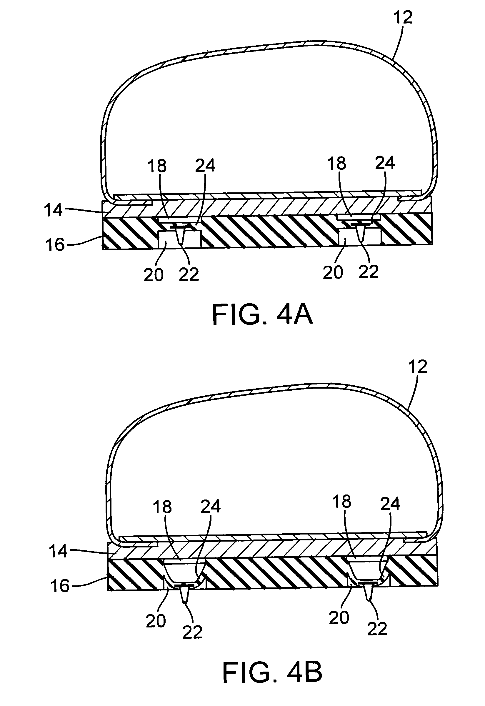
[0014]Reference is made to FIGS. 1–4 which illustrate a preferred embodiment of the invention. In FIG. 1 is shown a shoe having an upper body portion 10. The upper body portion can take any of a wide variety of forms but typically such a shoe would be of the type worn for sporting events such as golf, football, soccer and the like, i.e., sports played on turf, or of the type worn for outdoor and indoor use and in particularly in northern communities where outdoor use can involve walking or running on ice.

[0015]The upper body portion 10 will typically have a foot wrap 12 for the sides and upper foot and an upper sole portion 14 of semi-flexible / semi-stiff leather or molded rubber that is shaped to the contour of a wearer's foot bottom.

[0016]The portion of the shoe in which the features of the present invention are incorporated is the lower sole portion 16. As shown in FIGS. 1 and 2, the lower sole portion 16 is provided with a groove or channel 18 that substantially circumscribes the...


PUM


Abstract

A convertible shoe having a shoe body and a shoe sole. An air channel formed in said shoe sole including pressurized air inlet and air exhaust. An elongated pocket or multiple individual pockets in the bottom of the shoe sole and along said air channel. A flexible wall portion between said air channel and pocket that expands into the pocket(s) upon pressurization of said air channel. A protrusion affixed to said flexible wall portion and which extends out of said pocket and into engagement with a support surface when said air channel is pressurized.

Description

FIELD OF INVENTION[0001]This invention relates to a shoe that is provided with traction enhancing elements that can be extended and retracted to adapt the shoe to different support surfaces.BACKGROUND OF INVENTION[0002]Traction devices as contemplated for the present invention are often referred to generically as cleats. A cleated football shoe has different types of cleats that provide improved traction on different kinds of turf. A golf shoe has cleats that provide stability for a golfer when swinging a golf club. Not as common but considered to be as desirable are cleated shoes for walking on ice-laden walks and so on.[0003]The problem with such cleated shoes is that the cleats are not desirable on surfaces that either are impenetrable to the cleats or have surface finishes that can be damaged by the cleats (e.g., inside floors of homes, restaurants, club houses and the like).[0004]This dilemma has not gone unnoticed and there are numerous patents that have issued that purport to...

Claims


Application Information

Patent Timeline
Patent Type & Authority Patents(United States)
IPC IPC(8): A43C15/02
CPCA43B13/223A43C15/14A43C15/168
Inventor FOGARTY, STACY RENEEO'BRIEN, PATRICK MICHAELO'BRIEN, JOHN MICHAEL
Owner SELECT SOLE
Why Eureka
Try Eureka