
Card connector with anti-mismating device

a card connector and anti-mismation technology, applied in the direction of coupling device connection, engagement/disengagement of coupling parts, instruments, etc., can solve the problem of weakened stopper intensity, card connector, electrical card and even electronic appliances may be damaged, and improperly inserting electrical cards into the card connector

Inactive Publication Date: 2007-07-03
HON HAI PRECISION IND CO LTD
View PDF7 Cites 13 Cited by
  • Summary
  • Abstract
  • Description
  • Claims
  • Application Information

AI Technical Summary

Benefits of technology

[0009]To achieve the above object, a card connector comprises an insulating housing; a plurality of contacts retained in the insulating housing and a shell. The shell covers the insulating housing to define a card receiving space therebetween and defines a card insertion direction. The contacts comprise a plurality of contacting portions exposed into the card receiving space. A stopper is formed on the shell and protruding into the card receiving space and comprises a stopping portion approximately uprightly exposed into the card receiving space along the card insertion direction to prevent the card from mis-insertion.

Problems solved by technology

However, a user may insert the electrical card into the card connector in an improper state by mistake.
In this situation, the card connector, the electrical card and even the electronic appliance may be damaged.
When the card is properly inserted, the stopper will be accommodated in a slot formed in the card and does not prevent the card from inserting into the card connector to electrically connect with the contacts.
However, because the stopper uprightly arranges along the transverse direction, intensity of the stopper is weakened.
When the card is improper inserted some times by mistake, the stopper may be deflected from an original position due to collision of the card and does not prevent the card from electrically connecting with the contacts.

Method used


Image

  • Card connector with anti-mismating device
  • Card connector with anti-mismating device
  • Card connector with anti-mismating device

Examples


Embodiment Construction

[0016]Reference will now be made in detail to the preferred embodiment of the present invention.

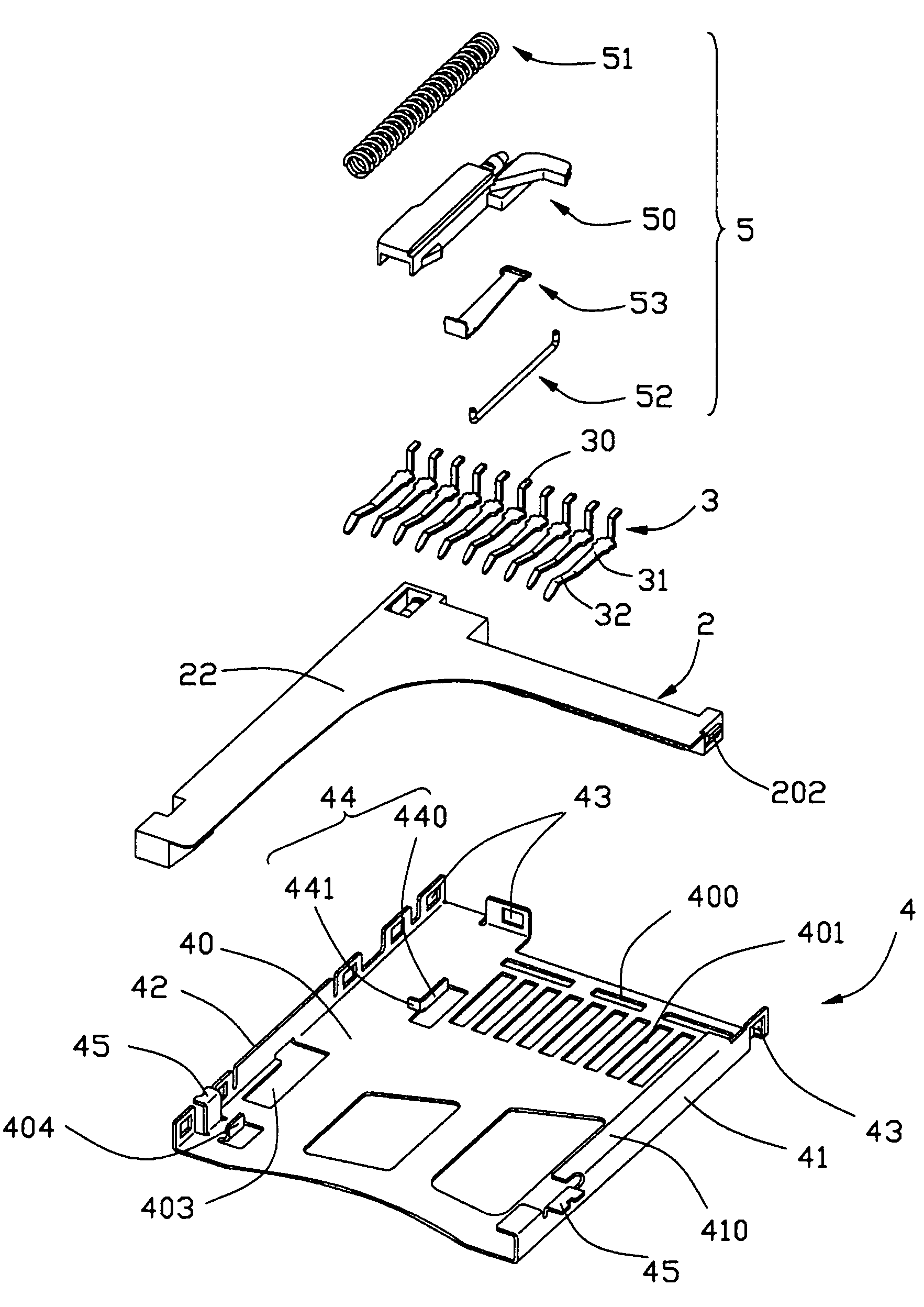
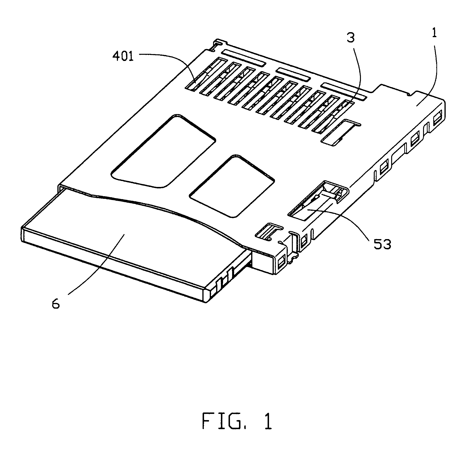
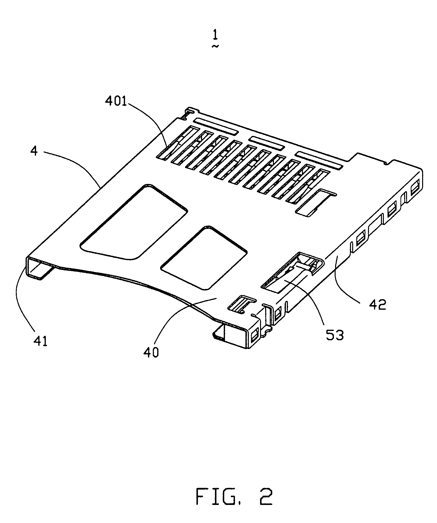
[0017]Referring to FIGS. 1–5, the card connector 1 of the present invention adapted for receiving a card 6 comprises an insulating housing 2, a plurality of contacts 3 received in the insulating housing 2, a shell 4 and an ejector 5.

[0018]Referring to FIGS. 4–5, the insulating housing 2 is approximately L-shaped, the insulating housing 2 comprises a rear wall 20, a right sidewall 21 extending forwardly from right end of the rear wall 20 and a bottom wall 22. The insulating housing 2 is formed with a plurality of wedges 202 on outside of the rear wall 20 and the sidewall 21. The rear wall 20 is formed with a plurality of bars 203 on upper face thereof and defines a plurality of receiving passages 200 running through the rear wall 20.

[0019]The shell 4 covers the insulating housing 2 and defines a card receiving space (not labeled) therebetween with an entrance opening (not labeled) at front...


PUM


Abstract

A card connector (1) includes an insulating housing (2); a number of contacts (3) retained in the insulating housing (2) and a shell (4). The shell (4) covers the insulating housing (2) to define a card receiving space therebetween and defines a card insertion direction. The contacts (3) comprise a number of contacting portions (32) exposed into the card receiving space. A stopper (44) is formed on the shell (4) and protruding into the card receiving space and comprises a stopping portion (440) approximately uprightly exposed into the card receiving space along the card insertion direction to prevent the card from mis-insertion.

Description

BACKGROUND OF THE INVENTION[0001]1. Field of the Invention[0002]The present invention is generally related to a card connector, and especially to a card connector with an anti-mismating device.[0003]2. Description of Related Art[0004]With the development of electronic appliances, different electrical cards are used to expand additional functions of the electronic appliance, such as data storage. A card connector is required to receive the electrical card to achieve the storage function between the electrical card and the corresponding electronic appliance. However, a user may insert the electrical card into the card connector in an improper state by mistake. In this situation, the card connector, the electrical card and even the electronic appliance may be damaged. Thus, one way to solve the above mention problem is to design the card connector with an anti-mismating device.[0005]A common card connector adapted for receiving a card comprises an insulating housing, a plurality of con...

Claims


Application Information

Patent Timeline
Patent Type & Authority Patents(United States)
IPC IPC(8): H01R24/00
CPCG06K13/08
Inventor WANG, HONG-LIANGZHANG, CHI
Owner HON HAI PRECISION IND CO LTD
Learn More