Residual staple amount detection device of electric stapler

a technology of amount detection and stapler, which is applied in the direction of stapling tools, manufacturing tools, nailing tools, etc., can solve the problem that the operator is not informed of an accurate remaining amount, and achieve the effect of accurately informing the remaining amount of staples inside the staple main body

Inactive Publication Date: 2007-07-10
MAX CO LTD
View PDF14 Cites 93 Cited by
  • Summary
  • Abstract
  • Description
  • Claims
  • Application Information

AI Technical Summary

Benefits of technology

[0004]It is a problem of the invention to provide a staple remaining amount detecting apparatus in an electric stapler resolving the above-described drawback and capable of informing a remaining amount of a staple at inside of a staple main body sufficiently accurately.

Problems solved by technology

Therefore, even when the remaining amount is small, a result of detection indicates as ‘present’ and when an electric stapler is provided to a copier or a printer, an operator is not informed of an accurate remaining amount.

Method used


Image

  • Residual staple amount detection device of electric stapler
  • Residual staple amount detection device of electric stapler
  • Residual staple amount detection device of electric stapler

Examples


Embodiment Construction

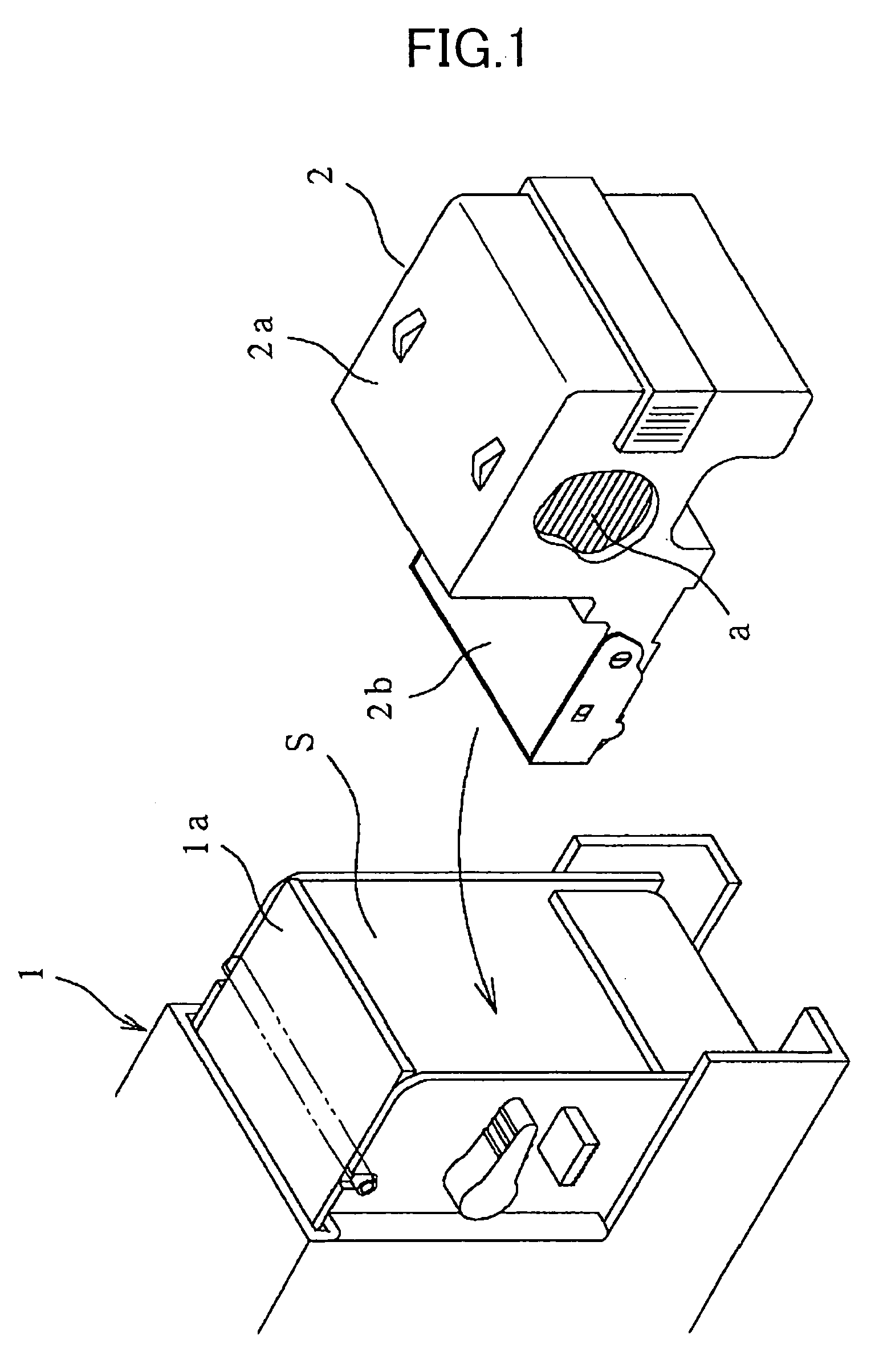
[0020]In FIG. 1, numeral 1 designates the electric stapler main body and numeral 2 designates the staple cartridge.

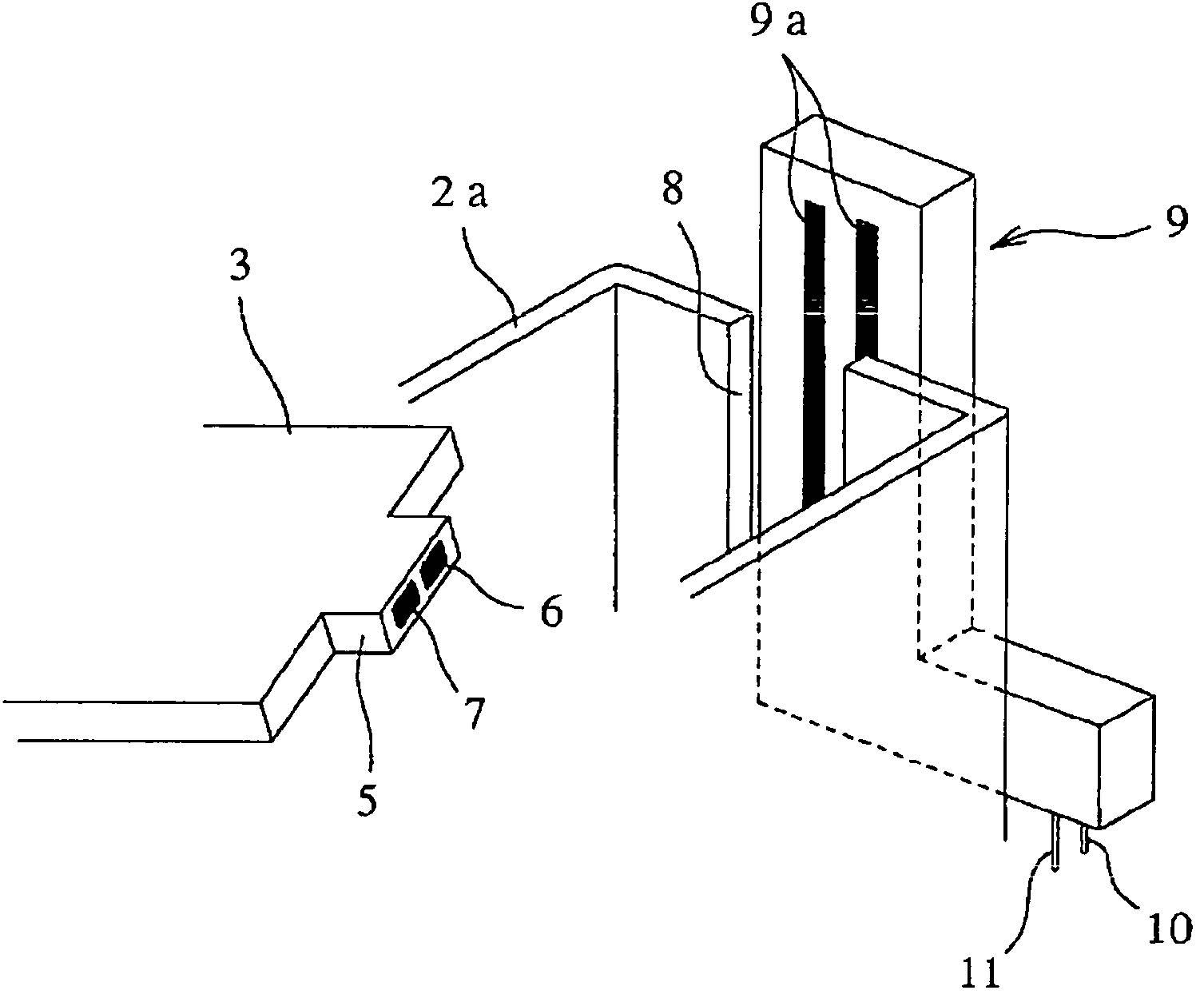
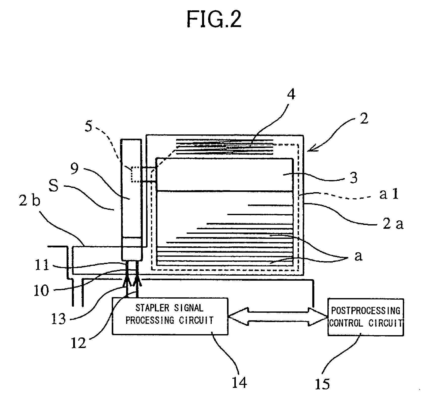
[0021]Sheet-like staples each constituted by connecting a number of staples in a straight form in a sheet-like shape are stacked in a plurality of layers to contain in a cartridge main body 2a of the staple cartridge 2. Further, as shown by FIG. 2, by a feed mechanism provided at the stapler main body 1, the sheet-like staples a are successively guided out to outside of a front guide 2b of the cartridge main body 2a from the sheet-like staple a at a lower end portion at inside of the cartridge main body 2a. Further, a magazine portion 1a of the stapler main body 1 is formed with a space s for mounting the cartridge 2. Further, the staple cartridge 2 is inserted to attach to the space s, the sheet staple a is fed frontwardly, both sides of the staple at the front end of the sheet staple a guided out from the front guide 2b are folded to bend and thereafter, penetrated th...


PUM

PropertyMeasurementUnit
voltageaaaaaaaaaa
shapeaaaaaaaaaa
electricalaaaaaaaaaa

Abstract

In an electric stapler which is attachably and detachably provided with a staple cartridge 2 attached and detached to and from a magazine portion of a stapler main body 1 and in which in the staple cartridge 2, sheet-like staples a each constituted by connecting a number of staples in a straight form in a sheet-like shape are contained in a cartridge main body 2a in a stacked shape, and the sheet-like staples a are successively guided out to outside of an opening portion of a lower end portion of a front wall of the cartridge main body 2a from the sheet-like staple a at a lower end portion, an engaging plate 3 engaged with the sheet-like staple a at a topmost portion is arranged at an upper portion of the cartridge main body 2a, an inner side or an outer side of the cartridge main body 2a is provided with position detecting mechanism 9 for detecting a position of the engaging plate 3, and a remaining amount of the sheet-like staples a is detected based on detection of the position by the position detecting mechanism 9.

Description

TECHNICAL FIELD[0001]The present invention relates to a staple remaining amount detecting apparatus in an electric stapler for detecting a remaining amount of a staple contained in a staple cartridge.BACKGROUND ART[0002]Generally, there is known an electric stapler in which a sheet staple constituted by connecting a number of staples in a straight form in a sheet-like shape is contained in a staple cartridge, the staple cartridge is inserted and detached into and from a path for mounting the cartridge formed at a magazine portion of a stapler main body, the staple cartridge is inserted to attach thereto and thereafter, both sides of a staple are successively folded to bend to strike out from a staple at a front portion of the sheet staple. According to such a system of an electric stapler, when a remaining amount of the sheet staple in the staple cartridge expires, the cartridge needs to be drawn out from the magazine portion to interchange by a new one thereof. For such a purpose, ...

Claims


Application Information

Patent Timeline
Patent Type & Authority Patents(United States)
IPC IPC(8): B27F7/11B27F7/28B25C5/16B27F7/38
CPCB25C5/1689B27F7/38
Inventor HIGUCHI, KAZUO
Owner MAX CO LTD
Why Eureka
Try Eureka