Alarm sensor

a technology of alarm sensor and sensor, which is applied in the field of sensors, can solve the problems of system alarm, possible, although extremely difficult, to defeat the sensor,

Active Publication Date: 2007-07-10
VOGT WILLIAM R
View PDF22 Cites 29 Cited by
  • Summary
  • Abstract
  • Description
  • Claims
  • Application Information

AI Technical Summary

Problems solved by technology

If an alarm system in which the sensor is incorporated is activated, this action will cause the system to go into alarm.
While this sensor configuration is commonly in use, it is possible, although extremely difficult, to defeat the sensor.

Method used


Image

  • Alarm sensor
  • Alarm sensor
  • Alarm sensor

Examples


Embodiment Construction

[0014]The following detailed description illustrates the invention by way of example and not by way of limitation. This description will clearly enable one skilled in the art to make and use the invention, and describes several embodiments, adaptations, variations, alternatives and uses of the invention, including what I presently believe is the best mode of carrying out the invention. As various changes could be made in the above constructions without departing from the scope of the invention, it is intended that all matter contained in the above description or shown in the accompanying drawings shall be interpreted as illustrative and not in a limiting sense.

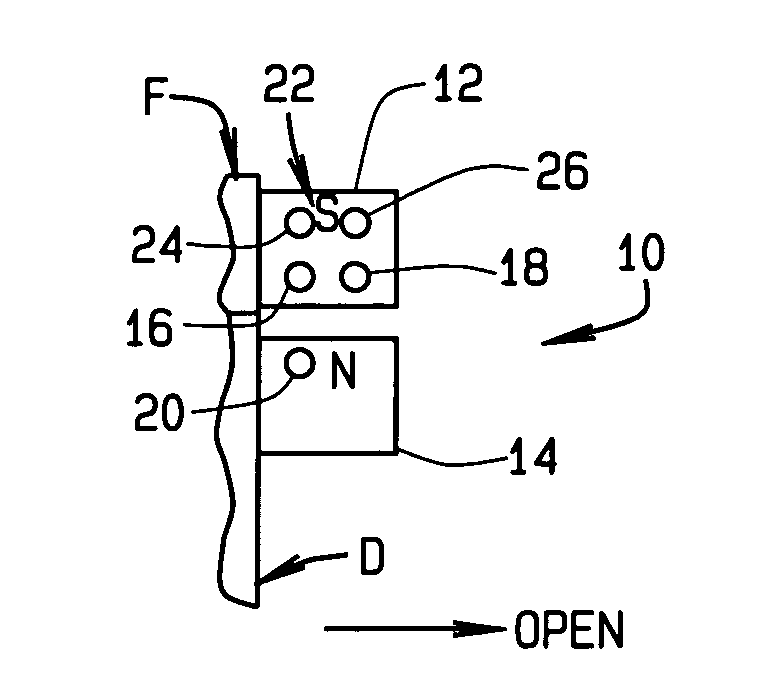
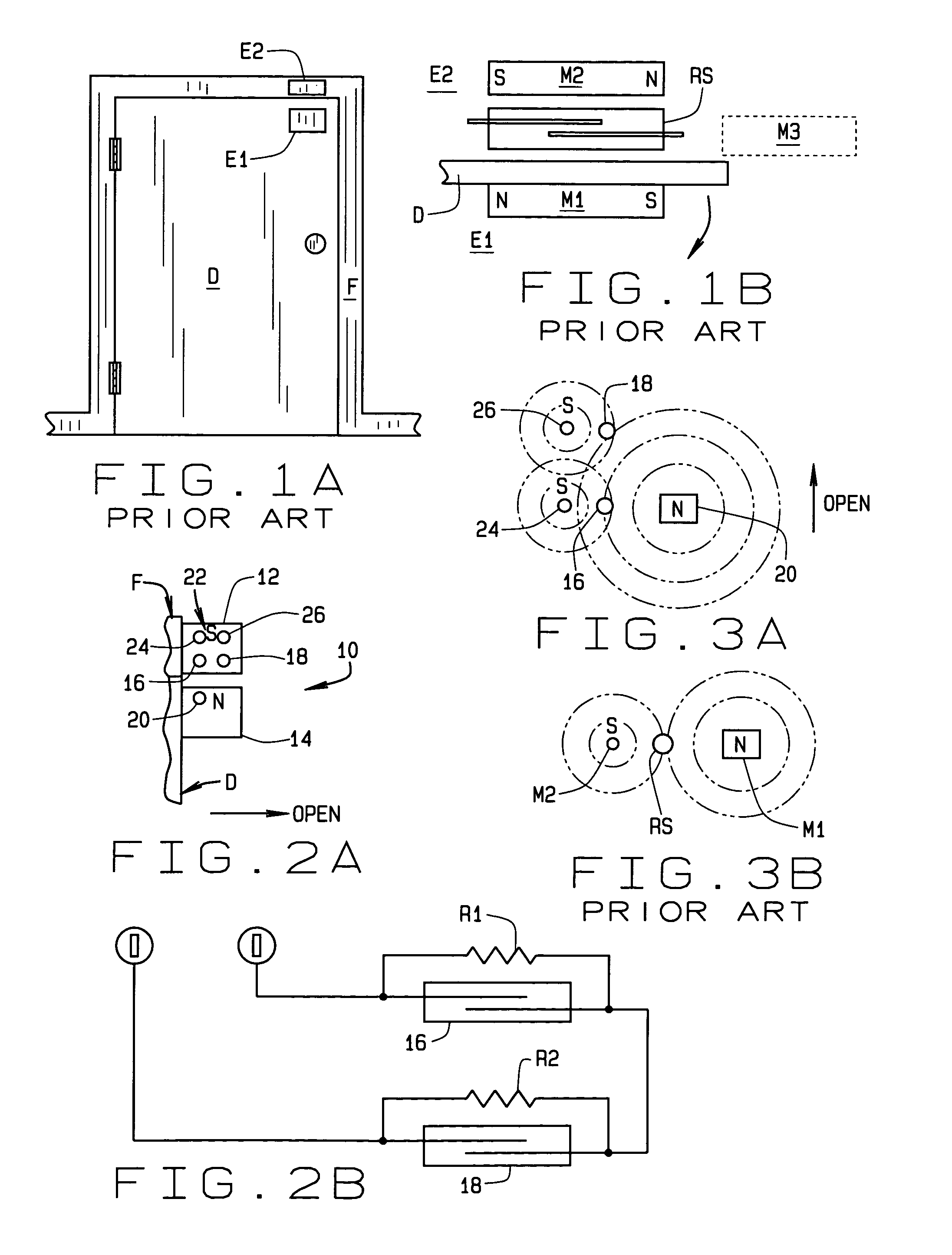
[0015]Referring to FIG. 2A, a sensor 10 of the present invention includes a housing 12 mounted on door frame or jamb F, for example, and a second housing 14 mounted on a movable object such as door D. The function of sensor 10 is to monitor movement of the door and place an alarm or security system in which the sensor is insta...


PUM


Abstract

An alarm system sensor (10) monitoring movement of an object (D) and placing the system into alarm when the object moves more than a predetermined distance from a predetermined position. First and second reed switches (16, 18) are located in a predetermined orientation relative to each other and in tandem to the object. Bias magnets (24, 26) are used with the reed switches. A magnet (20) is movable with the object and produces a force simultaneously sensed by both reed switches. This force maintains both reed switches in a state keeping the alarm system in a non-alarm condition so long as the object substantially remains in its predetermined position. The object, when it moves, moves toward one of the reed switches and away from the other reed switch. Movement of the object more than the predetermined distance results in the force sensed by one of the reed switches increasing and the force sensed by the other reed switch decreasing. Either change in sensed force activates the appropriate reed switch causing the alarm system to go into alarm.

Description

CROSS REFERENCE TO RELATED APPLICATIONS[0001]NoneSTATEMENT REGARDING FEDERALLY SPONSORED RESEARCH OR DEVELOPMENT[0002]N / ABACKGROUND OF THE INVENTION[0003]This invention relates to sensors for monitoring the position of a door or the like; and, more particularly, to a tandem sensor for use in such monitoring and which cannot be readily defeated.[0004]In security systems for monitoring a premises, a sensor is often used with a door or window to provide an indication when the door, for example, is open when it shouldn't be. One type of sensor used for this purpose utilizes a reed switch. As shown in FIG. 1A, a door D is monitored by a sensor S comprised of a first element E1 attached to the door and moving with the door as it opens and closes, and a second element E2 which is permanently affixed to a door frame or jamb F. In FIG. 1B, element E1 is shown to include a magnet M1 which is installed in a housing mounted on the door. Element E2 is shown to include both a magnet M2 and a reed...

Claims


Application Information

Patent Timeline
Patent Type & Authority Patents(United States)
IPC IPC(8): G08B13/08
CPCG08B13/08H01H36/0046
Inventor VOGT, WILLIAM R.
Owner VOGT WILLIAM R
Why Eureka
Try Eureka