Bag with flap for bag-in-box container system

a bag-in-box container and bag-in-box technology, which is applied in the direction of flexible containers, sacks, packaging, etc., can solve the problems of affecting the complete emptying of the bag. achieve the effect of facilitating the complete emptying of the bag

Inactive Publication Date: 2007-07-17
CDF CORP
View PDF18 Cites 19 Cited by
  • Summary
  • Abstract
  • Description
  • Claims
  • Application Information

AI Technical Summary

Benefits of technology

[0010]The primary object of this invention is to provide a bulk storage bag of the kind having a drain with an improved form of tab for use in supporting the bag so as to facilitate complete emptying of its contents via the drain.

Problems solved by technology

Regardless of the type of bag in the box, if the bag is large, e.g., a bag having a volume of about 275 gallons, complete removal of all of the liquid or particulate material from the bag is difficult.
The problem of removing all of the contents is noticeably difficult in the case of viscous liquids.
Depending on the form of bag construction, complete emptying of the bag may be impeded by its size or shape, the location of its drain and / or the fact that as its contents are discharged, the evacuated portion of the bag tends to collapse.
However, a problem arises in using the Wilcox invention for emptying plastic bags that have a generally cubic or rectangular parallelepiped shape when filled, e.g., substantially self-supporting bags like those disclosed in U.S. Pat. No. 5,788,121, cited supra, since those bags are difficult to grasp with a noose.
Unfortunately the structural integrity of the foregoing tab construction is limited by the strength of the seal made by the end panels with the ends of the tube.
Those seals are narrow and when the tab is wound on the windlass shaft, the weight of the bag and its contents tend to stress the top end panel to the extent that it may tear or separate where it is joined to the tube.
That method of making a bag with a flap is labor intensive and hence costly.

Method used


Image

  • Bag with flap for bag-in-box container system
  • Bag with flap for bag-in-box container system
  • Bag with flap for bag-in-box container system

Examples


Embodiment Construction

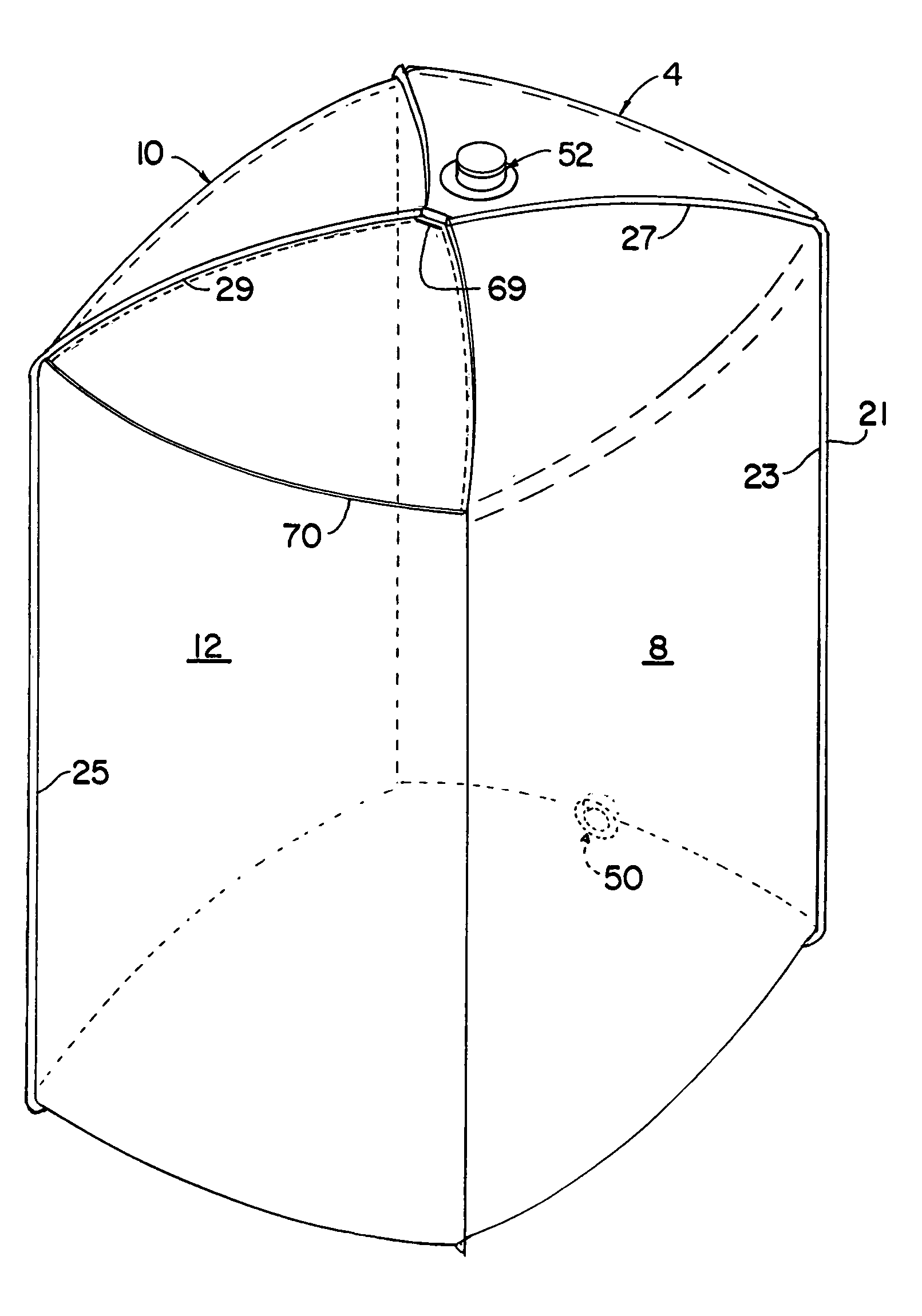
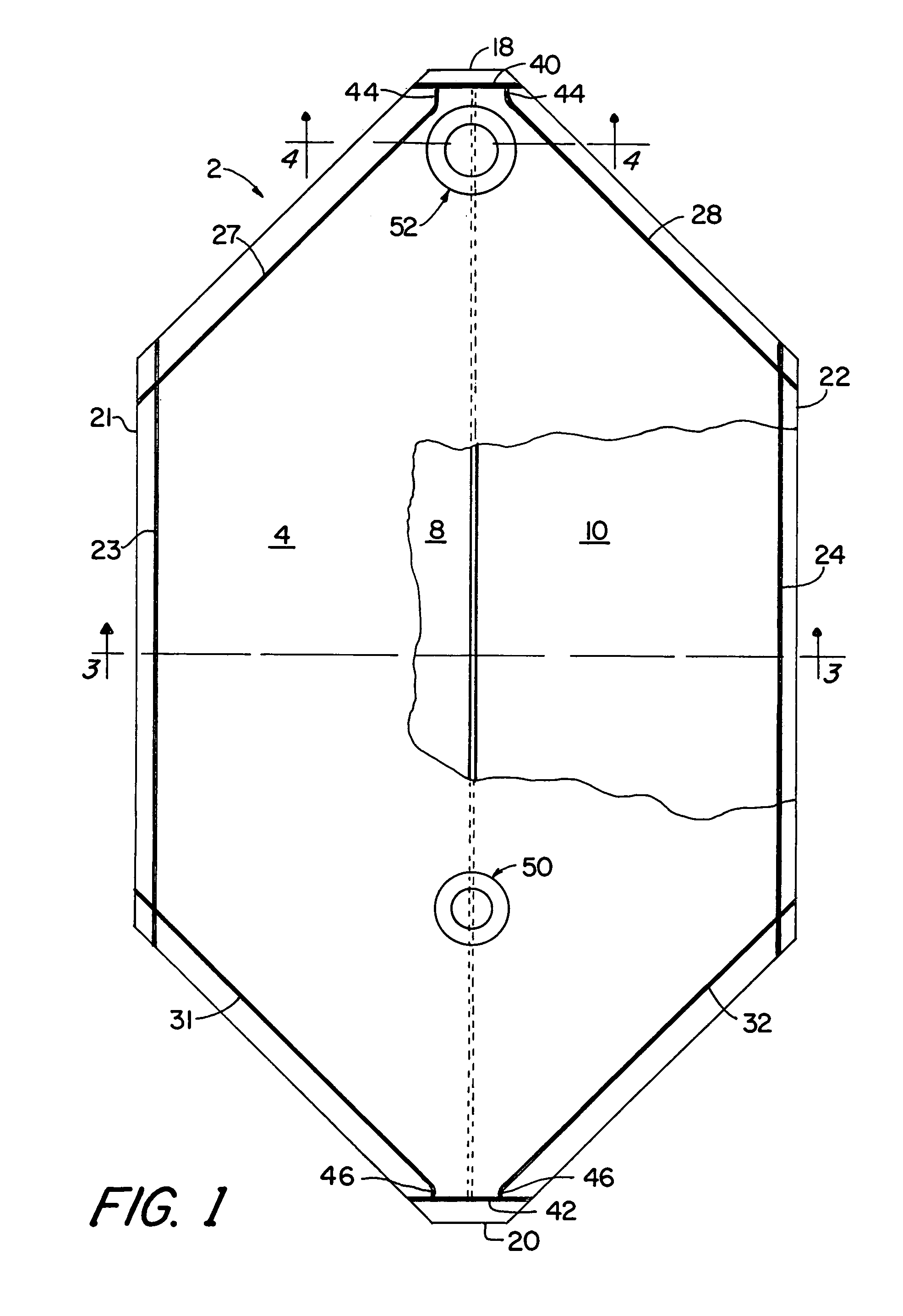
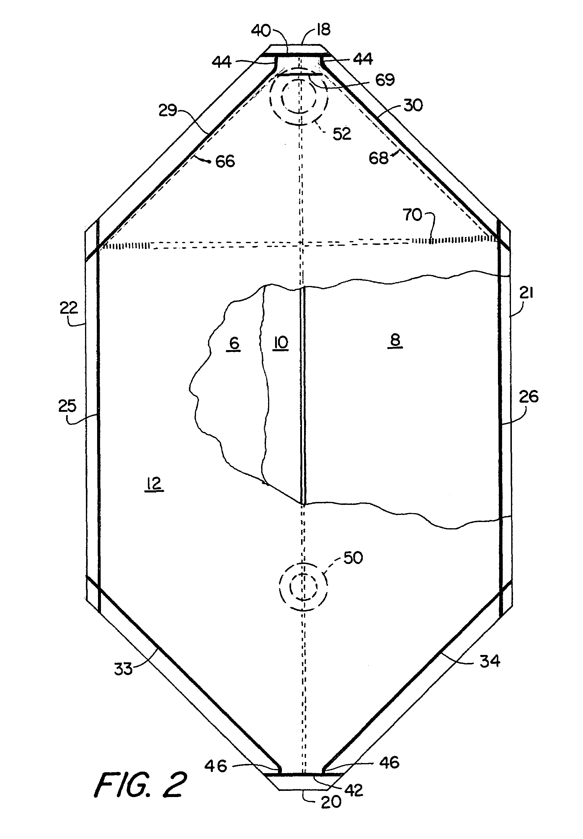
[0025]The preferred embodiment of the invention is a four side-seal type bag 2 composed of five discrete portions or panels 4, 6, 8, 10 and 12 of flexible, heat-sealable packaging material in sheet form. The packaging material is impervious to water and also preferably to oils and other liquid materials. By way of example but not limitation, the packaging sheet material may consist of polyethylene or polypropylene or some other thermoplastic material or be a laminate of two or more packaging materials bonded to one another. Each of the portions or panels 4-12 may comprise a single sheet of packaging material (“single ply”) or two or more sheets of packaging material (“multi-ply”). In the case of multi-ply portions, the individual sheets (“plies”) may be of like or different material and, as is rendered obvious by the following detailed description, they are secured to one another only in selected areas. The preferred embodiment is a two-ply bag. For convenience and simplicity of ill...


PUM

PropertyMeasurementUnit
volumeaaaaaaaaaa
volumeaaaaaaaaaa
flexibleaaaaaaaaaa

Abstract

A bag for storing material in liquid or particulate form, comprising four side walls and top and bottom walls that are integral extensions of the four side walls, is characterized by an additional single or multi-ply sheet that overlies and is sealed to one side of said bag, said sheet material being adapted to be partially separated from itself so as to form a flap at the top end of the bag that can be gripped for use in supporting the bag as it is being drained of its contents via a drain located at the bottom end of the bag.

Description

FIELD OF INVENTION[0001]This invention relates to flexible bags for use in bag-in-box container systems, and more particularly to means for facilitating removal of viscous or powdery materials from a bag in a box.BACKGROUND OF THE INVENTION[0002]In recent years a number of industries have adopted the bag-in-box concept for storing and transporting liquid and particulate commodities in relatively large quantities. For example, the bag-in-box has been employed for transporting in bulk such diverse products as vegetable oils, salad dressings, syrups, soy sauce, peanut butter, pharmaceuticals, talc, motor oil, industrial chemicals, detergents in liquid or powder form, and toiletry products or ingredients. The bag-in box concept comprises a flexible bag that is chemically resistant and impermeable to water and air and serves as the container for a selected commodity, and a box that serves as a protective container for the bag and its contents. By way of example, a bag used for shipping c...

Claims


Application Information

Patent Timeline
Patent Type & Authority Patents(United States)
IPC IPC(8): B65D33/14B65D30/08B65D30/20B65D33/16B65D75/56B65D77/06
CPCB65D75/563B65D77/065B65D2575/565Y10S383/906
Inventor SULLIVAN, JR., JOSEPH J.
Owner CDF CORP
Why Eureka
Try Eureka