Method and apparatus for providing an interface mechanism for a computer simulation

a computer simulation and interface mechanism technology, applied in the direction of mechanical control devices, manual control with single controlling member, instruments, etc., can solve the problems of severe spinal headaches of patients, damage to the spinal cord, and high surgical complexity, and achieve high-realism motion and force feedback, reduce friction, and reduce backlash of the system

Inactive Publication Date: 2007-07-31
IMMERSION CORPORATION
View PDF311 Cites 137 Cited by
  • Summary
  • Abstract
  • Description
  • Claims
  • Application Information

AI Technical Summary

Benefits of technology

[0015]The present invention provides a mechanical interface apparatus and method which can provide highly realistic motion and force feedback to a user of the apparatus. The preferred apparatus includes a gimbal mechanism which provides degrees of freedom to a user manipulatable object about a remote pivot point such that the gimbal mechanism is entirely within a single hemisphere of a spherical workspace of the user object. In addition, a band drive mechanism provides mechanical advantage in applying force feedback to the user, smooth motion, and reduction of friction, compliance, and backlash of the system. The present invention is particularly well suited to simulations of medical procedures using specialized tools, as well as simulations of other activities, video games, etc.
[0021]The interface apparatus of the present invention provides a unique gimbal mechanism having a remote pivot point that allows a user manipulatable object to be positioned on one side of the pivot point and the gimbal mechanism entirely on the other side of the pivot point. This provides a greater workspace for the user object and allows the mechanism to be protected and concealed. In other embodiments, the remote pivot point allows the user object to be rotated about the center of the object while advantageously allowing the user to completely grasp the object. Furthermore, the present invention includes easy-to-assemble band drive mechanisms that provide very low friction and backlash and high bandwidth forces to the user object, and are thus quite suitable for high precision simulations such as medial procedures. The structure of the apparatus permits transducers to be positioned such that their intertial contribution to the system is very low, thus enhancing the haptic response of the apparatus even further. Finally, a simulation process allows for realistic simulation of precise procedures such as epidural anesthesia. These advantages allow a computer system to have more complete and realistic control over force feedback sensations experienced by a user of the apparatus.

Problems solved by technology

For example, epidural anesthesia is a highly delicate procedure performed by anesthesiologists in operations.
Overshooting the epidural space may result in a “wet tap” puncturing the dura mater, resulting in severe spinal headaches for the patient, or, in extreme cases, damage to the spinal cord.
Currently there is no practical and effective training tool to assist trainees in developing proficiency in the administration of epidural anesthesia and like medical procedures.
Mannequins and cadavers often do not meet many of the needs of trainees for such precise manipulations.
However, none of these devices is tailored for such precise operations as epidural anesthesia.
Since actuators which supply realistic force feedback tend to be large and heavy, they often provide inertial constraints.
There is also the problem of coupled actuators.
While it is possible to ground all of the actuators in a serial chain by using a complex transmission of cables or belts, the end result is a low stiffness, high friction, high damping transmission which corrupts the bandwidth of the system, providing the user with an unresponsive and inaccurate interface.
These types of interfaces also introduce tactile “noise” to the user through friction and compliance in signal transmission and limit the degree of sensitivity conveyed to the user through the actuators of the device.
However, these systems are not easily applicable to simulation environments such as those needed for medical procedures or simulations of vehicles and the like, since the forces applied to the user are with reference to the body of the user, not to a manipulated instrument or control, and the absolute location of the user's appendages or a manipulated instrument are not easily calculated.
Furthermore, these devices tend to be complex mechanisms in which many actuators must be used to provide force feedback to the user.
In addition, existing force feedback devices are typically bulky and require that at least a portion of the force feedback mechanism extend into the workspace of the manipulated medical instrument.
This can cause natural actions during the medical procedure, such as placing one's free hand on the skin surface when inserting a needle, to be strained, awkward, or impossible and thus reduces the realism of the simulation.
In addition, the mechanism intrudes into the workspace of the instrument, reducing the workspace of the instrument and the effectiveness and realism of many force feedback simulations and video games.
Furthermore, this undesired extension into the workspace often does not allow the force feedback mechanism to be easily housed in a protective casing and concealed from the user.
Furthermore, prior force feedback devices often employ low fidelity actuation transmission systems, such as gear drives.
However, these systems require that a drive capstan be wrapped several times with a cable and that the cable be accurately tensioned, resulting in considerable assembly time of the force feedback device.
There is also energy loss associated with the cable deflection as the capstan turns.

Method used


Image

  • Method and apparatus for providing an interface mechanism for a computer simulation
  • Method and apparatus for providing an interface mechanism for a computer simulation
  • Method and apparatus for providing an interface mechanism for a computer simulation

Examples


Embodiment Construction

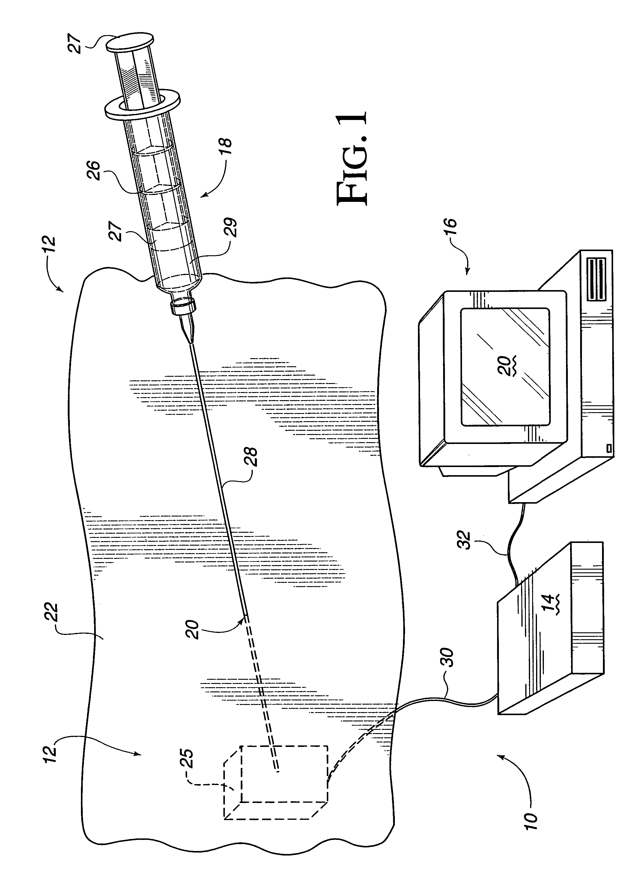
[0035]In FIG. 1, a virtual reality system 10 used to simulate a medical procedure includes a human / computer interface apparatus12, an electronic interface 14, and a computer 16. The illustrated virtual reality system 10 is directed to a virtual reality simulation of a needle insertion procedure. An example of control software used in the simulation is provided in Appendix A. Suitable software drivers which interface such simulation software with computer input / output (I / O) devices are available from Immersion Human Interface Corporation of San Jose, Calif.

[0036]A needle / syringe tool (or “needle”) 18 used in conjunction with one embodiment of the present invention is manipulated by an operator and, optionally, virtual reality images (and / or instructions or procedure information) may optionally be displayed on a screen 20 of the computer in response to such manipulations (or on a 3-D goggle display worn by the operator). Preferably, the computer 16 is a personal computer or workstatio...


PUM


Abstract

A mechanical interface for providing high bandwidth and low noise mechanical input and output for computer systems. A gimbal mechanism includes multiple members that are pivotably coupled to each other to provide two revolute degrees of freedom to a user manipulatable about a pivot point located remotely from the members at about an intersection of the axes of rotation of the members. A linear axis member, coupled to the user object, is coupled to at least one of the members, extends through the remote pivot point and is movable in the two rotary degrees of freedom and a third linear degree of freedom. Transducers associated with the provided degrees of freedom include sensors and actuators and provide an electromechanical interface between the object and a computer. Capstan band drive mechanisms transmit forces between the transducers and the object and include a capstan and flat bands, where the flat bands transmit motion and force between the capstan and interface members. Applications include simulations of medical procedures, e.g. epidural anesthesia, where the user object is a needle or other medical instrument, or other types of simulations or games.

Description

CROSS REFERENCE TO RELATED APPLICATION[0001]This application is a Continuation of U.S. application Ser. No. 09 / 448,536, filed Nov. 22, 1999 now U.S. Pat. No. 6,705,871, which is a continuation of U.S. application Ser. No. 08 / 709,012, filed Sep. 6, 1996, now U.S. Pat. No. 6,024,576, each of which is incorporated herein by reference in its entirety.BACKGROUND OF THE INVENTION[0002]The present invention relates generally to mechanical interface devices between humans and computers, and more particularly to mechanical devices for tracking manual manipulations and providing simulated force feedback.[0003]Virtual reality computer systems provide users with the illusion that they are part of a “virtual” environment. A virtual reality system will typically include a computer processor, such as a personal computer or workstation, specialized virtual reality software, and virtual reality I / O devices such as display screens, head mounted displays, sensor gloves, etc. As virtual reality systems...

Claims


Application Information

Patent Timeline
Patent Type & Authority Patents(United States)
IPC IPC(8): G09B23/28G09G5/00A61B19/00G05G9/04
CPCA61B19/22G05G9/04G06F3/016G06F3/0338G06F3/05G09B23/285A61B2019/2242A61B2019/2276A61B2019/2292A61B2034/742A61B34/70A61B34/71A61B34/76
Inventor BEVIRT, JOEBENMOORE, DAVID F.NORWOOD, JOHN Q.ROSENBERG, LOUIS B.LEVIN, MIKE D.
Owner IMMERSION CORPORATION
Why Eureka
Try Eureka