Closure panel arrangement

a technology for closing panels and wing accessories, applied in the direction of power plant inspection panels, machines/engines, wing accessories, etc., can solve the problems of affecting the effect of wing assembly, unable to properly form a pivot association,

Inactive Publication Date: 2007-08-14
ROLLS ROYCE PLC
View PDF25 Cites 38 Cited by
  • Summary
  • Abstract
  • Description
  • Claims
  • Application Information

AI Technical Summary

Benefits of technology

[0017]Typically, the bias is secured to the closure panel and/or other parts

Problems solved by technology

Unfortunately, such detachment of the closure panel from the hinge edge requires upon reassembly accurate association between that hinge edge and a pivot edge of the closure panel in order to create the necessary pivot association between the pin and hook-like clasps.
Sometimes this pivot association may not be appropriately formed by failure to ensure engagement

Method used


Image

  • Closure panel arrangement
  • Closure panel arrangement
  • Closure panel arrangement

Examples


Embodiment Construction

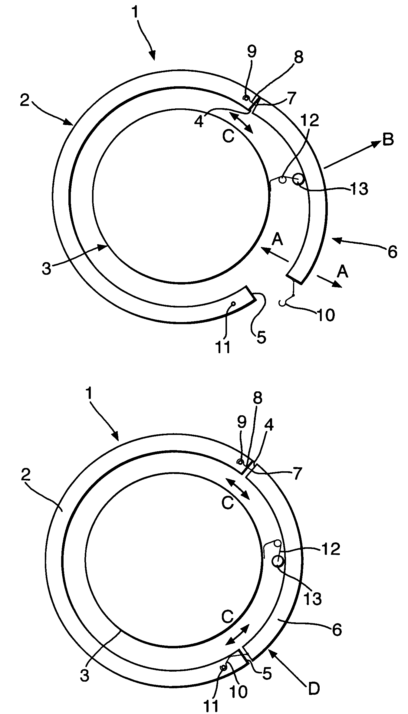
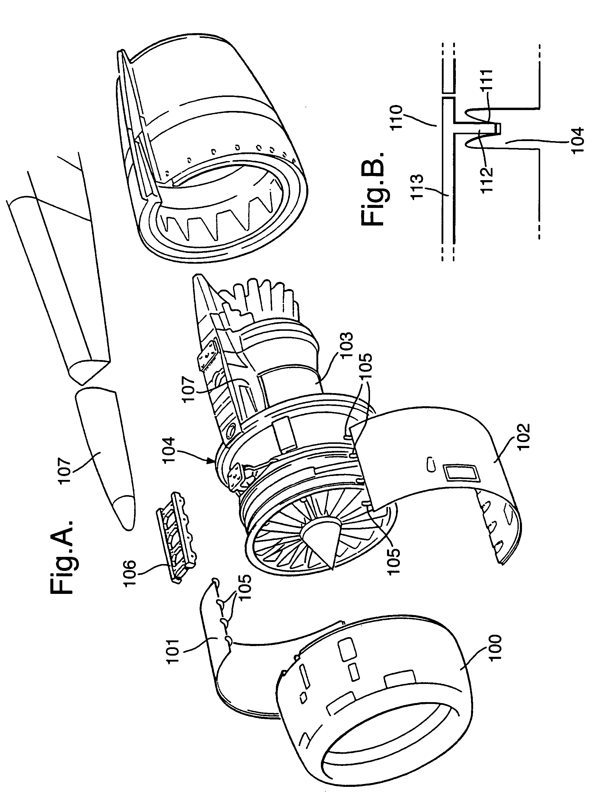
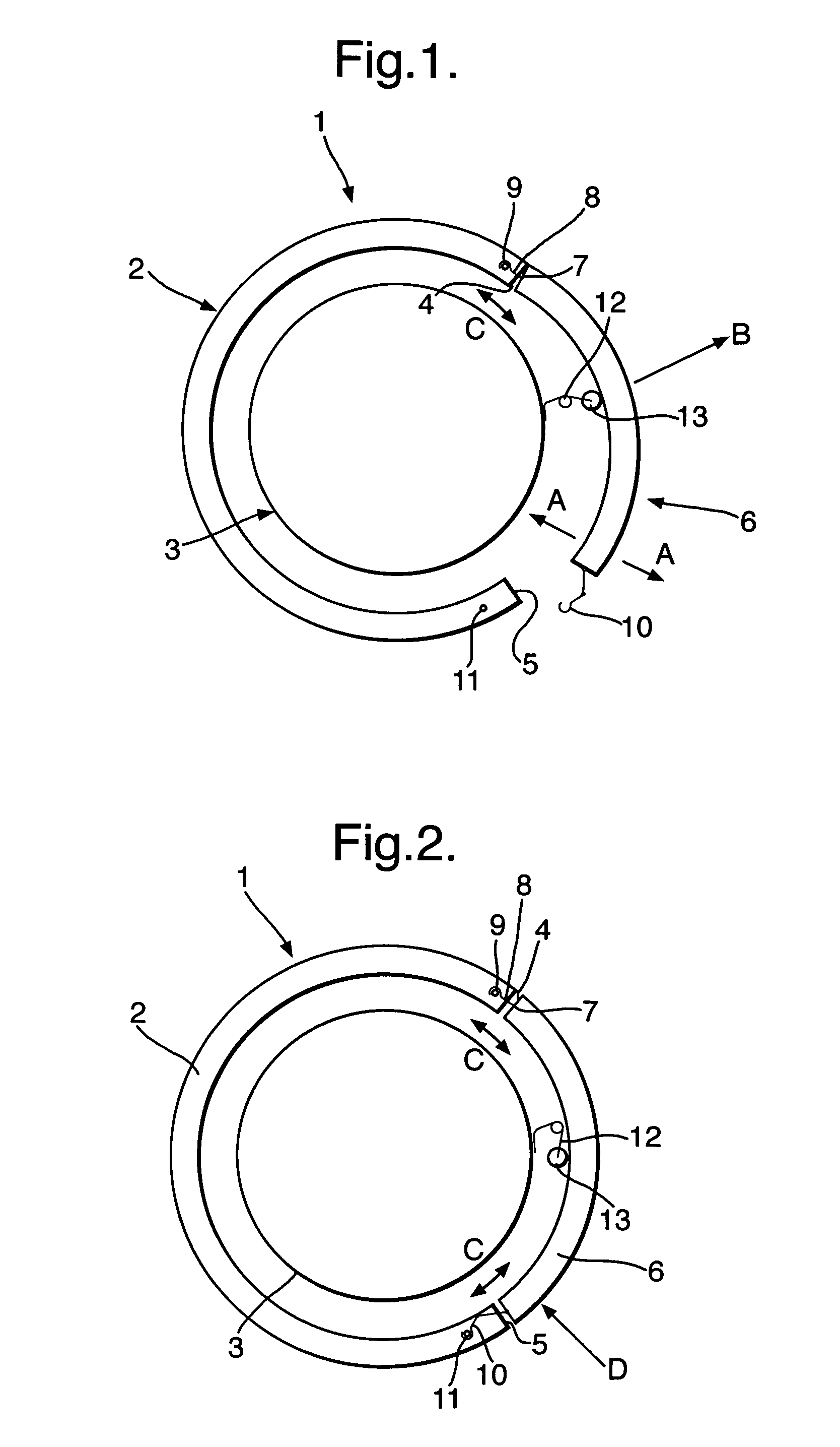
[0027]As indicated above there are a number of situations where it is necessary to secure a closure panel over an aperture, opening or gap particularly with regard to aircraft engines and airframes. These openings or gaps are provided in cowlings and fairings in order to allow access for maintenance and repair and possibly during initial assembly and installation. Typically these closure panels will be secured about one side whereby the panel can pivot into position and then be locked by a latch in that position. Unfortunately the latch alone or in association by friction with adjacent panels may retain position even when not properly aligned and secured when there is limited vibration or load stresses placed upon the closure arrangement. However, the panel will fall out when such loads are applied.

[0028]Pivot is generally achieved through a number of hook clasps associated with a pin. Normally, the pin is in the fixed housing structure whilst the hook clasps are located upon a hing...


PUM


Abstract

A closure panel arrangement is provided in which a closure panel 6 can only be retained when appropriately aligned with engagement between clasp hooks 8 and pins 9 is achieved along with association between latch hooks 10 and pins 11. If there is not appropriate association and alignment then a bias 12, 22, 32, 42 creates an outward bias force upon the closure panel 6 whereby the panel 6 will continue to fall out. In such circumstances, the panel 6 cannot remain in position due to simply key fit interference/friction association of sufficient strength for non-operational conditions but which will fail during operation due to vibration or stresses.

Description

FIELD OF THE INVENTION[0001]The present invention relates to a closure panel arrangement and more particularly to a closure panel arrangement used in fairings or cowlings of an aircraft engine or air frame.BACKGROUND OF THE INVENTION[0002]In order to gain access for repair and maintenance it is necessary to provide removable panels in the form of fairings or closures about engine structures or airframes. Accordingly, these panels must be easily removable, but also must be securely located whereby the panel will not become detached in use causing damage to associated engine parts or airframes, both of the aircraft upon which the panel is secure as well as other aircraft in the vicinity.[0003]Previously, it has been known to provide hinged panels which extend from a hinge edge of an opening or gap. Thus, the panel can pivot about that hinge edge until securely located normally by an opposed latching edge of the opening or gap. Normally, the closure panel is secured about a pin with a ...

Claims


Application Information

Patent Timeline
IPC IPC(8): B64C1/16B64D29/06B64D29/08F01D25/24
CPCB64D29/06B64D29/08F01D25/24F05D2230/80
Inventor MAYES, HAROLD G
Owner ROLLS ROYCE PLC
Why Eureka
Try Eureka