Safety switch

a safety switch and switch technology, applied in the field of switches, can solve the problems of insufficient electrical outlets in rooms to connect multiple electric appliances, electric appliances may probably burn out, and insufficient electrical outlets in rooms

Active Publication Date: 2007-08-21
HUANG ALBERT
View PDF7 Cites 6 Cited by
  • Summary
  • Abstract
  • Description
  • Claims
  • Application Information

AI Technical Summary

Benefits of technology

[0010]The main objective of the invention is to provide a safety switch that is mounted on a power strip including a power-s

Problems solved by technology

However, electrical outlets are usually mounted securely in a wall or floor and cannot be moved.
As the number of electrical appliances proliferated to include lamps, TVs, tape and disk players

Method used


Image

  • Safety switch
  • Safety switch
  • Safety switch

Examples


Embodiment Construction

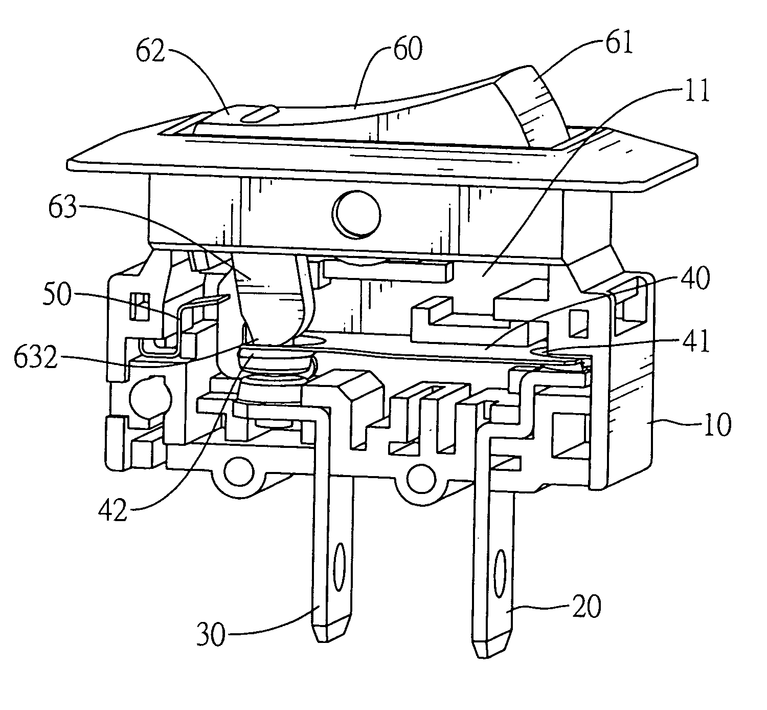
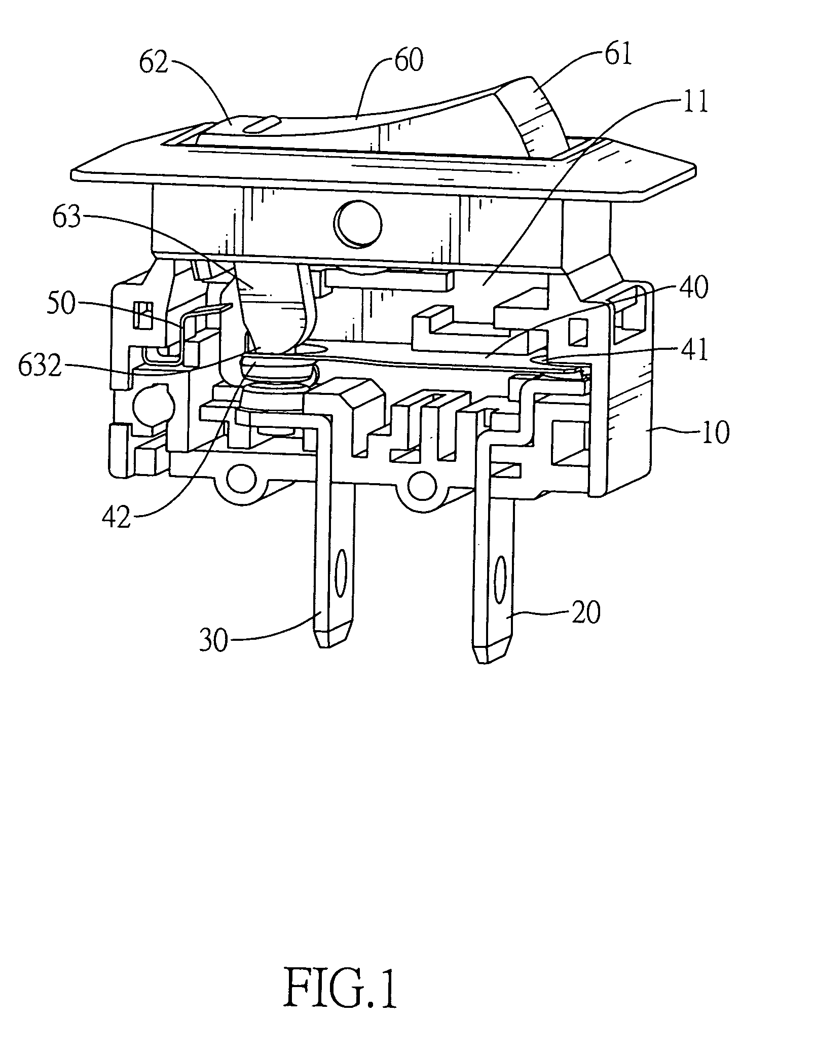
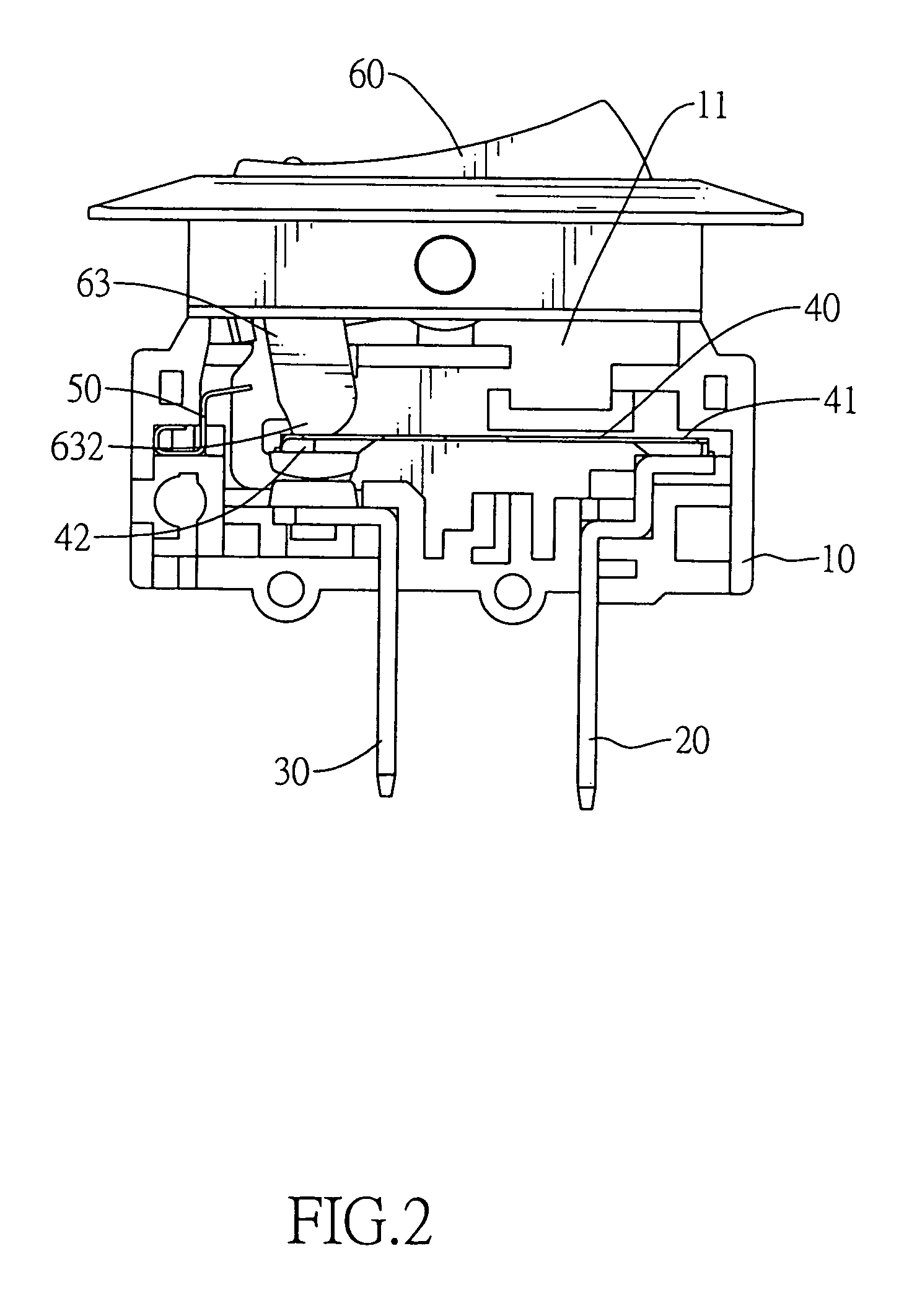
[0026]With reference to FIGS. 1 and 2, safety switches in accordance with the present invention are mounted on a power strip having a power-supplying circuit and multiple receptacles. The receptacles are mounted on the power strip, connect respectively to the safety switches and may respectively hold power plugs of electric appliances.

[0027]Each safety switch comprises a casing (10), a first circuit prong (20), a second circuit prong (30), a switch contact (40), a rocker (60) and a latch (50).

[0028]The casing (10) has a top, a bottom and a cavity (11). The cavity (11) is defined in the casing (10).

[0029]The first circuit prong (20) is mounted in the cavity (11), extends through the bottom of the casing (10) and electrically connects to the power-supplying circuit in the power strip.

[0030]The second circuit prong (30) is mounted in the cavity (11), extends through the bottom of the casing (10) parallel to the first circuit prong (20) and electrically connects to the power-supplying c...


PUM


Abstract

A safety switch has a casing, a first circuit prong, a second circuit prong, a switch contact, a rocker, an arm and a latch. The first and second circuit prongs are mounted in and extend through the casing. The switch contact bends upward when temperature of the switch contact increases, is mounted on the first circuit prong and has a distal end selectively contacting the second circuit prong. The rocker is pivotally mounted on the casing and has a deactivating end and an activating end. The arm is formed on and protrudes down from the activating end and connects to the distal end of the switch contact. The latch is mounted in the cavity and selectively locks the arm to prevent the distal end of the switch contact from contacting the second circuit prong as the temperature drops. The safety switch may be used in severely cold environments.

Description

BACKGROUND OF THE INVENTION[0001]1. Field of the Invention[0002]The present invention relates to a switch, and more particularly to a safety switch that is mounted on a power strip including a power-supplying circuit and is capable of cutting off the power-supplying circuit when circuit current on the power-supplying circuit is too high.[0003]2. Description of Related Art[0004]Electric appliances connect to and obtain power from electrical outlets. However, electrical outlets are usually mounted securely in a wall or floor and cannot be moved. Therefore, an electric appliance having a wire and plug connected to the electrical outlet had to be positioned near the electrical outlet. As the number of electrical appliances proliferated to include lamps, TVs, tape and disk players, stereos, clocks, computers, computer peripherals, etc., electrical outlets in rooms is insufficient to connect multiple electric appliances.[0005]Therefore, a power strip having multiple receptacles and an ext...

Claims


Application Information

Patent Timeline
IPC IPC(8): H01H21/00
CPCH01H23/24H01H37/323H01H37/52
Inventor HUANG, ALBERT
Owner HUANG ALBERT
Why Eureka
Try Eureka