Aerosol product dispenser

a technology of product dispensers and dispensers, which is applied in the field of dispensers, can solve the problems of cumbersome dispensers of this type, affecting the balance of dispensers, and so as to achieve the effect of reducing the energy of spray and hence the distance and spread of spray

Active Publication Date: 2007-09-04
IDEAVILLABE PROD
View PDF18 Cites 12 Cited by
  • Summary
  • Abstract
  • Description
  • Claims
  • Application Information

AI Technical Summary

Problems solved by technology

Redirecting the spray in that manner diminishes the energy of the spray and hence the distance and spread of the spray.
Dispensers of that type are cumbersome because the canister is not received within the body of the dispenser but instead hangs down from the bottom of the dispenser.
The dispensers are therefore not properly balanced, making them difficult to manipulate.
Further, those dispensers tend not to be aesthetically pleasing in appearance.
However, given the need to securely engage the canister to retain the canister when fully loaded, the canister engagement mechanisms of the prior art dispensers are often difficult to release to permit the canister to be disengaged.

Method used


Image

  • Aerosol product dispenser
  • Aerosol product dispenser
  • Aerosol product dispenser

Examples


Embodiment Construction

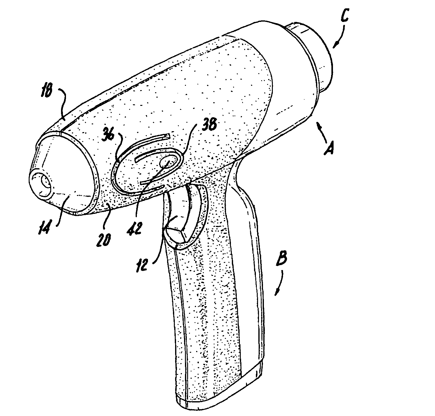
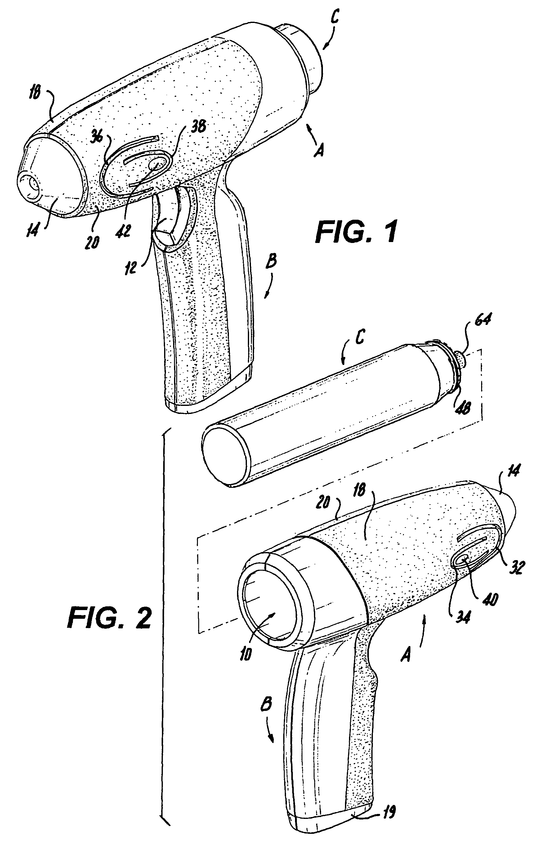
[0046]As best seen from FIGS. 1, 2 and 3, the dispenser of the present invention has a generally pistol-like shaped housing, including a substantially cylindrical, hollow open-ended body, generally designated A, and a downwardly extending handle, generally designated B. A pressurized product-containing canister, generally designated C, is inserted into body A through a rear opening 10 therein, as seen in FIG. 2.

[0047]Situated within the housing is an actuator, generally designated D, which includes a trigger 12, a nose part 14 and a generally cylindrical hollow part 16 which connects trigger 12 to nose part 14. Preferably, trigger 12, nose part 14 and connecting part 16 are integral.

[0048]As is apparent from FIG. 3, the dispenser is formed of mirror image plastic ejection molded housing halves 18, 20, each having a body section and a handle section. The housing halves are joined together to form the housing by any conventional means, such as protrusion 22 and a boss 24 defining a pr...


PUM


Abstract

The apparatus is designed to dispense an aerosol product from a pressurized cylindrical cannister having a depressible nozzle at one end. The dispenser is pistol-shaped, formed of a generally cylindrical body and a downwardly extending handle with a trigger. The body defines an elongated recess adapted to receive and engage the cannister, with the nozzle situated substantially along the axis of the body. The dispenser body has a nose part moveably mounted in the front end. Means are provided for connecting the trigger to move the nose part relative to the body to depress the canister nozzle such that the product is released through an opening in the nose part.

Description

CROSS-REFERENCE TO RELATED APPLICATIONS[0001]This application is based upon Provisional Application Ser. No. 60 / 589,483, filed Jul. 19, 2004 and priority thereon is hereby claimedSTATEMENT REGARDING FEDERALLY SPONSORED RESEARCH OR DEVELOPMENT[0002]Not ApplicableREFERENCE TO A “SEQUENCE LISTING”, A TABLE, OR A COMPUTER PROGRAM LISTING APPENDIX SUBMITTED ON COMPACT DISC[0003]Not ApplicableBACKGROUND OF THE INVENTION[0004]1. Field of the Invention[0005]The present invention relates to dispensers for spraying aerosol products supplied in pressurized canisters and more particularly to a pistol-shaped dispenser that receives the canister and is trigger actuated to release the product spray in a direction along the axis of the canister.[0006]2. Description of Prior Art Including Information Disclosed Under 37 CFR 1.97 and 1.98[0007]Many types of dispensers are known for dispensing aerosol products from pressurized canisters that have a top mounted axial stem which is depressible to release...

Claims


Application Information

Patent Timeline
Patent Type & Authority Patents(United States)
IPC IPC(8): G01F11/10B05B7/02
CPCB65D83/384
Inventor KHUBANI, ANANDSZYMANSKI, AARON
Owner IDEAVILLABE PROD
Why Eureka
Try Eureka