
Chair ride mechanism with tension assembly

a technology of tension assembly and seat, which is applied in the field of task chairs, can solve the problems of increasing the difficulty of chair manufacture, the overall weight of the chair, and the overall cost of the chair, and the manual adjustment of the existing tension mechanism is often confusing and tedious for the user

Inactive Publication Date: 2007-09-25
KIMBALL INTERNATIONAL
View PDF29 Cites 124 Cited by
  • Summary
  • Abstract
  • Description
  • Claims
  • Application Information

AI Technical Summary

Benefits of technology

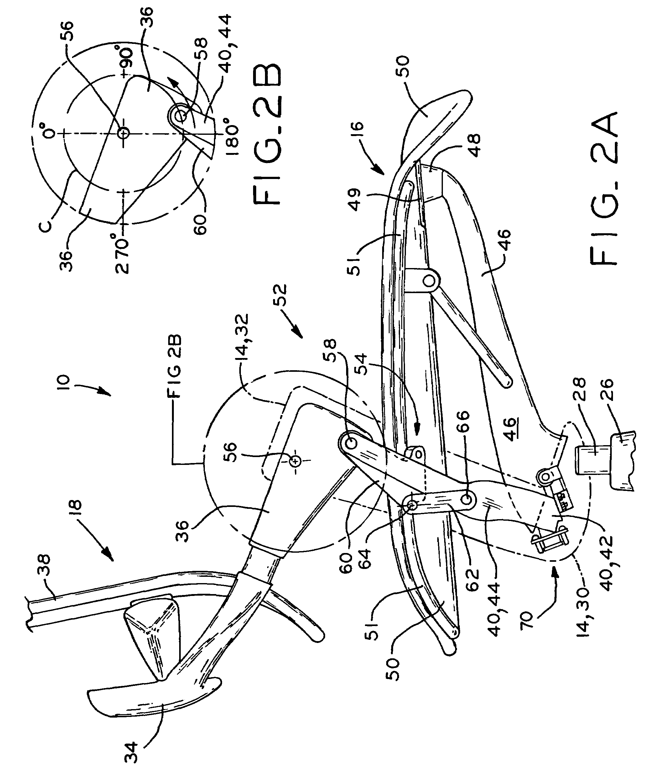
[0009]The present invention provides a task chair, including a backrest assembly and a seat assembly pivotally coupled both to one another and to side portions of a fixed yoke member for synchronized movement, in which the seat of the seat assembly moves upwardly and forwardly concurrently with recline of the backrest of the backrest assembly. The chair further includes a tension assembly including an elongate tension member, such as a leaf spring, secured at one end thereof to the yoke member, and a contact member, such as a contact roller, adjustably mounted to the seat assembly. The contact member engages the tension member such that the tension member resists recline of the backrest assembly and concurrent movement of the seat assembly from their initial positions, and also provides a restoring force which tends to move the backrest to its initial upright position and the seat to its initial rearward and lowered position. The contact member is adjustable with respect to the tension member in order to vary the effective moment arm acting upon the tension member, thereby varying the pre-load of the tension member and the resistance provided by the tension member.

Problems solved by technology

A disadvantage of this arrangement is that, upon reclining movement of the seated user, the user is moved slightly downwardly and away from a desk or other work surface near which the user is seated, and the user's line of sight is also shifted downwardly, requiring the user to adjust their head position to maintain a line of sight to a computer monitor, for example.
Also, the adjustment mechanism for varying the tension of the coil spring typically requires a large number of mechanical components contained within the control housing, increasing the difficulty of manufacture of the chair, the overall cost of the chair, and the overall weight of the chair.
Further, manual adjustment of existing tension mechanisms is often confusing and tedious for the user, often requiring a user to rotate an adjustment knob over a very large number of turns.

Method used


Image

  • Chair ride mechanism with tension assembly
  • Chair ride mechanism with tension assembly
  • Chair ride mechanism with tension assembly

Examples


Embodiment Construction

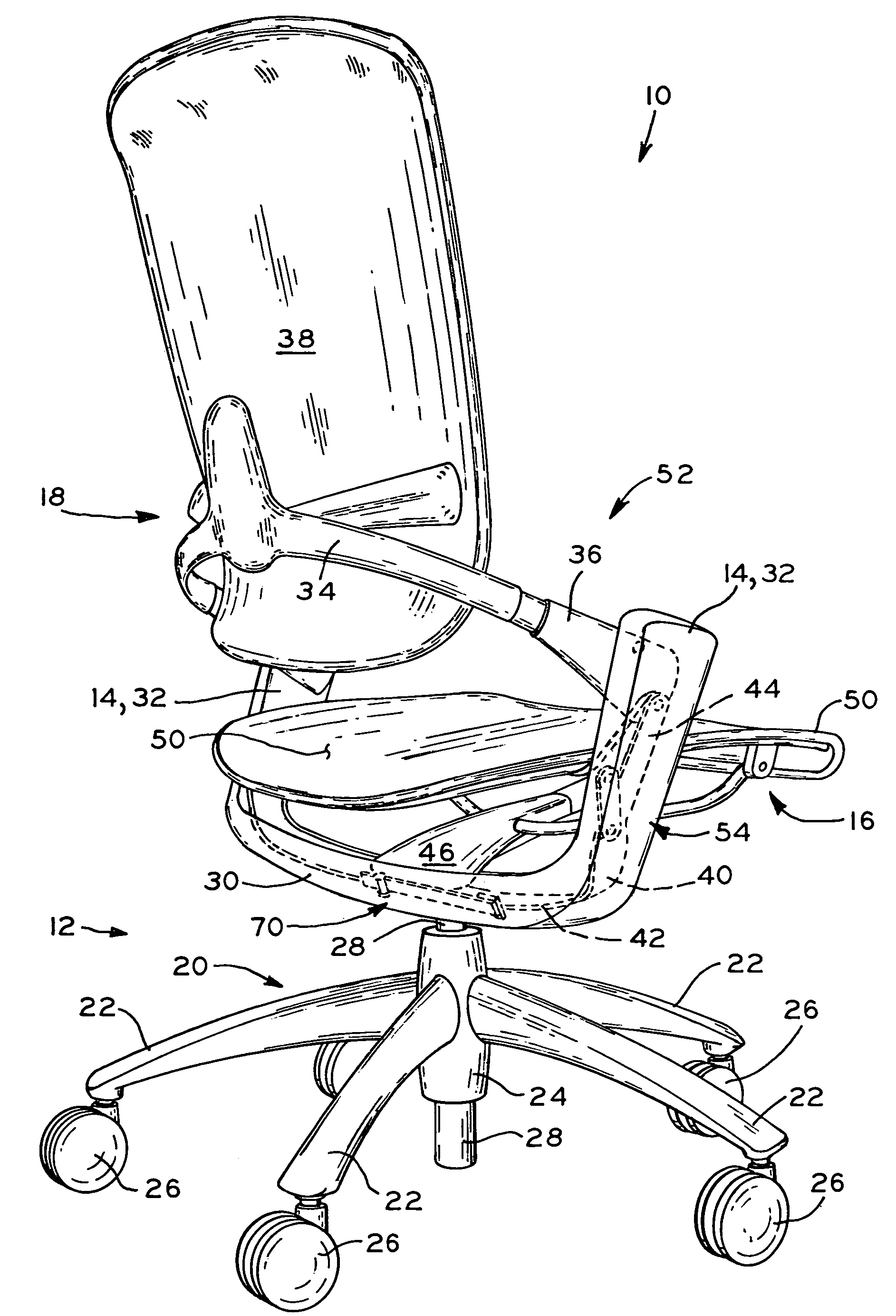
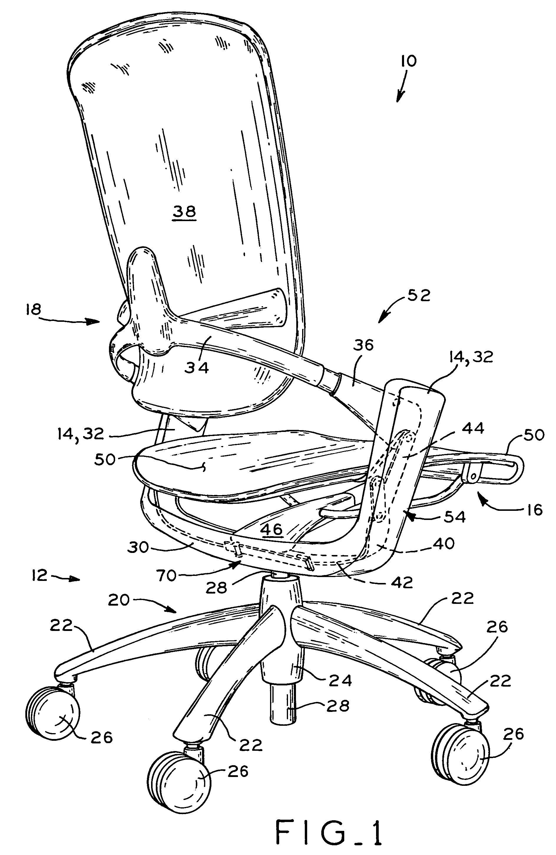
[0024]Referring to FIG. 1, task chair 10 is shown, which generally includes pedestal or base assembly 12, a primary frame or yoke member 14 mounted to base assembly 12, and seat assembly 16 and backrest assembly 18 pivotally mounted to one another and to yoke member 14 for synchronized movement as described below. Base assembly 12 generally includes chair base 20 having a plurality of arms 22 projecting from hub 24, with arms 22 having caster wheels 26 at the ends thereof for rolling movement of chair 10 along a floor surface. Hub 24 of chair base 20 is fitted with a pneumatic cylinder 28 having an upper end thereof secured to yoke member 14 to provide vertical height adjustment of yoke member 14, seat assembly 16, and backrest assembly 18 with respect to base assembly 12 in a manner well known in the art.

[0025]Yoke member 14 generally includes transverse beam 30 and a pair of upwardly-extending side portions 32 at opposite ends of transverse beam 30. The upper end of pneumatic cyli...


PUM


Abstract

A task chair, including a backrest assembly and a seat assembly pivotally coupled both to one another and to side portions of a fixed yoke member for synchronized movement, in which the seat of the seat assembly moves upwardly and forwardly concurrently with recline of the backrest of the backrest assembly. The chair further includes a tension assembly including an elongate tension member, such as a leaf spring, secured at one end thereof to the yoke member, and a contact member, such as a contact roller, adjustably mounted to the seat assembly. The contact member engages the tension member such that the tension member resists recline of the backrest assembly and concurrent movement of the seat assembly from their initial positions, and also provides a restoring force which tends to move the backrest to its initial upright position and the seat to its initial rearward and lowered position. The contact member is adjustable with respect to the tension member in order to vary the effective moment arm acting upon the tension member, thereby varying the pre-load of the tension member and the resistance provided by the tension member.

Description

CROSS REFERENCE TO RELATED APPLICATIONS[0001]This application claims the benefit under 35 U.S.C. § 119(e) of U.S. Provisional Patent Application Ser. No. 60 / 578,233, entitled CHAIR RIDE MECHANISM WITH TENSION ASSEMBLY, filed on Jun. 9, 2004.BACKGROUND OF THE INVENTION[0002]1. Field of the Invention[0003]The present invention relates to task chairs, and in particular, to a ride mechanism for a task chair, the ride mechanism including an adjustable tension assembly.[0004]2. Description of the Related Art[0005]Task chairs are commonly used by persons while working in a seated position in an office or other occupational environment. Typically, such chairs include a base assembly with caster wheels for rolling movement over a floor surface, a pneumatic cylinder connecting the base assembly to the seat assembly for vertical adjustment, as well as a number of manual adjustment features to allow the user to adjust the movement characteristics of the chair to a desired configuration.[0006]So...

Claims


Application Information

Patent Timeline
Patent Type & Authority Patents(United States)
IPC IPC(8): A47C1/024A47C1/02A47C1/032A47C1/06A47C1/12A61G15/00B60N2/00
CPCA47C1/03222A47C1/03255A47C1/03266A47C1/03277
Inventor DEIMEN, MICHAEL LHATCHER, STEPHEN D
Owner KIMBALL INTERNATIONAL
Learn More