Tissue accessing and anchoring device and method

a tissue accessing and tissue technology, applied in the field of medical devices and methods, can solve the problems of exposing physicians to accidental injury during tissue excision, affecting the accuracy of surgical procedures, so as to improve the anchoring and demarcation of the location, avoid delay and imprecision, and simplify and reduce the cost of such procedures.

Inactive Publication Date: 2007-10-16
SENORX
View PDF229 Cites 14 Cited by
  • Summary
  • Abstract
  • Description
  • Claims
  • Application Information

AI Technical Summary

Benefits of technology

[0018]The devices, methods and systems of the invention provide the advantages of locating and accessing a desired location within a patient's body with a single device which may be directly anchored at the location. Including these capabilities in a single device avoids the delay and imprecision in anchoring a device at a proper location that results from the use of multiple devices for these functions. Moreover, the methods and devices of the present invention are suitable for use outside of an operating room, simplifying and reducing the cost of such procedures. In addition, the coiling of the anchoring elements serves to shield the sharp tips, protecting physicians from possible injury during excision of a patient's tissue. The present invention thus provides improved devices for marking and excising a sentinel lymph node that has accumulated radiation and is suspected of harboring cancerous tissue. In addition, the devices provide anchoring elements that radially extend through a substantial angular extent to provide improved anchoring and demarcation of a location within a patient's body.

Problems solved by technology

It should be noted that total axillary lymph node dissection can be an extremely painful and debilitating procedure for patients who often suffer from severe lymph edema as a result of the body's inability to channel the flow of lymph fluid once most or all of the lymph nodes have been excised.
Such wires may have exposed, sharp ends to cut into tissue, and may expose physicians to accidental injury during excision of tissue.

Method used


Image

  • Tissue accessing and anchoring device and method
  • Tissue accessing and anchoring device and method
  • Tissue accessing and anchoring device and method

Examples


Embodiment Construction

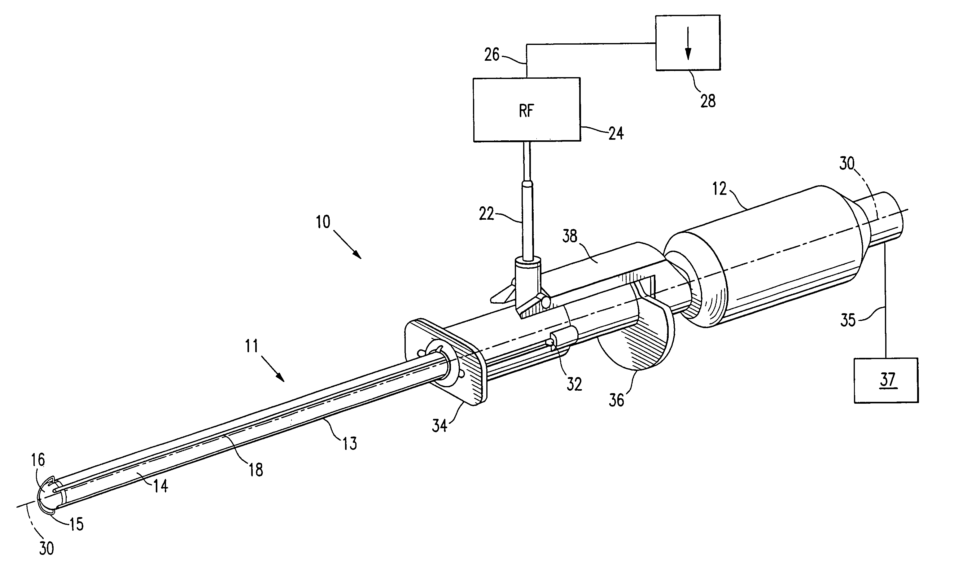
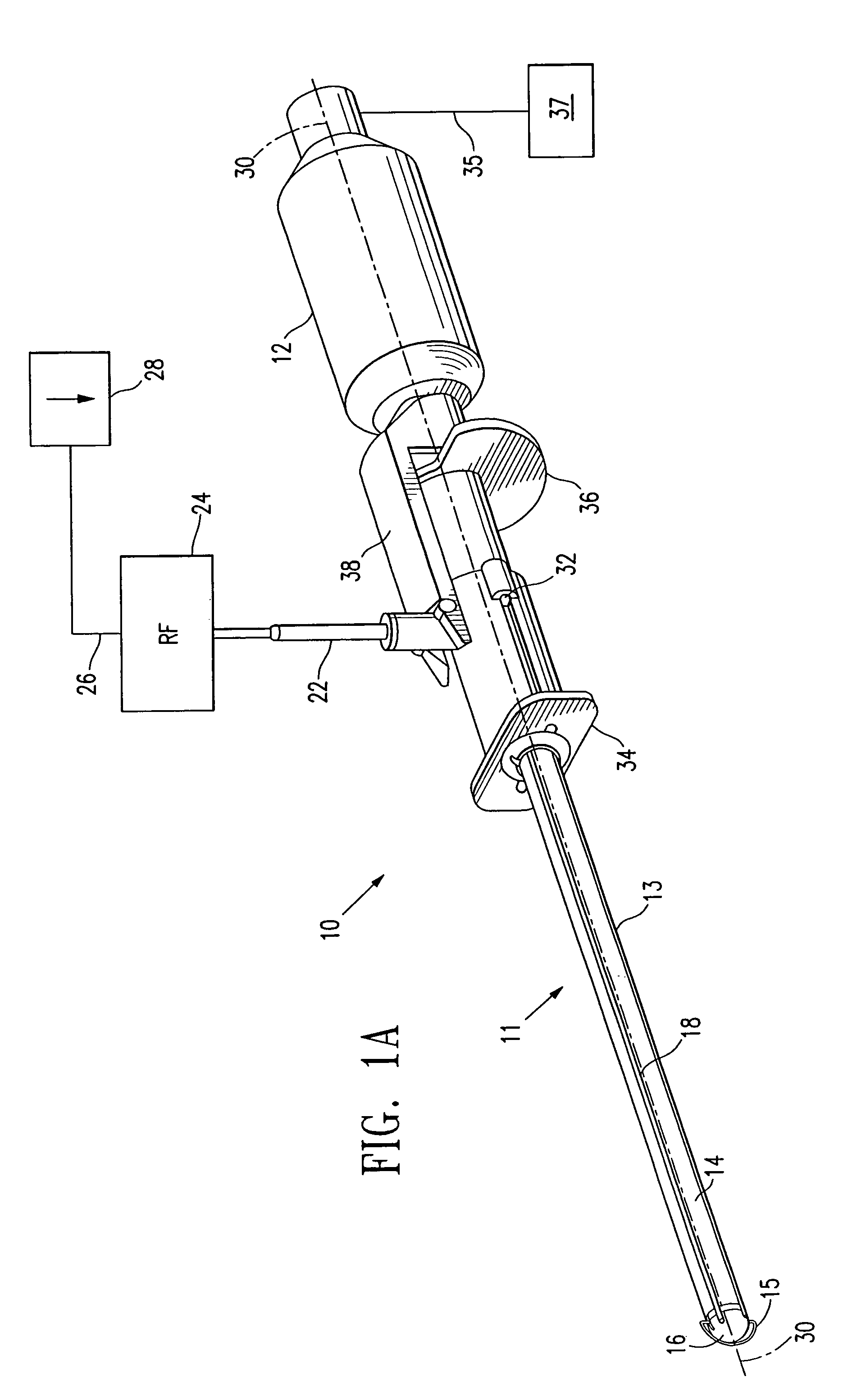
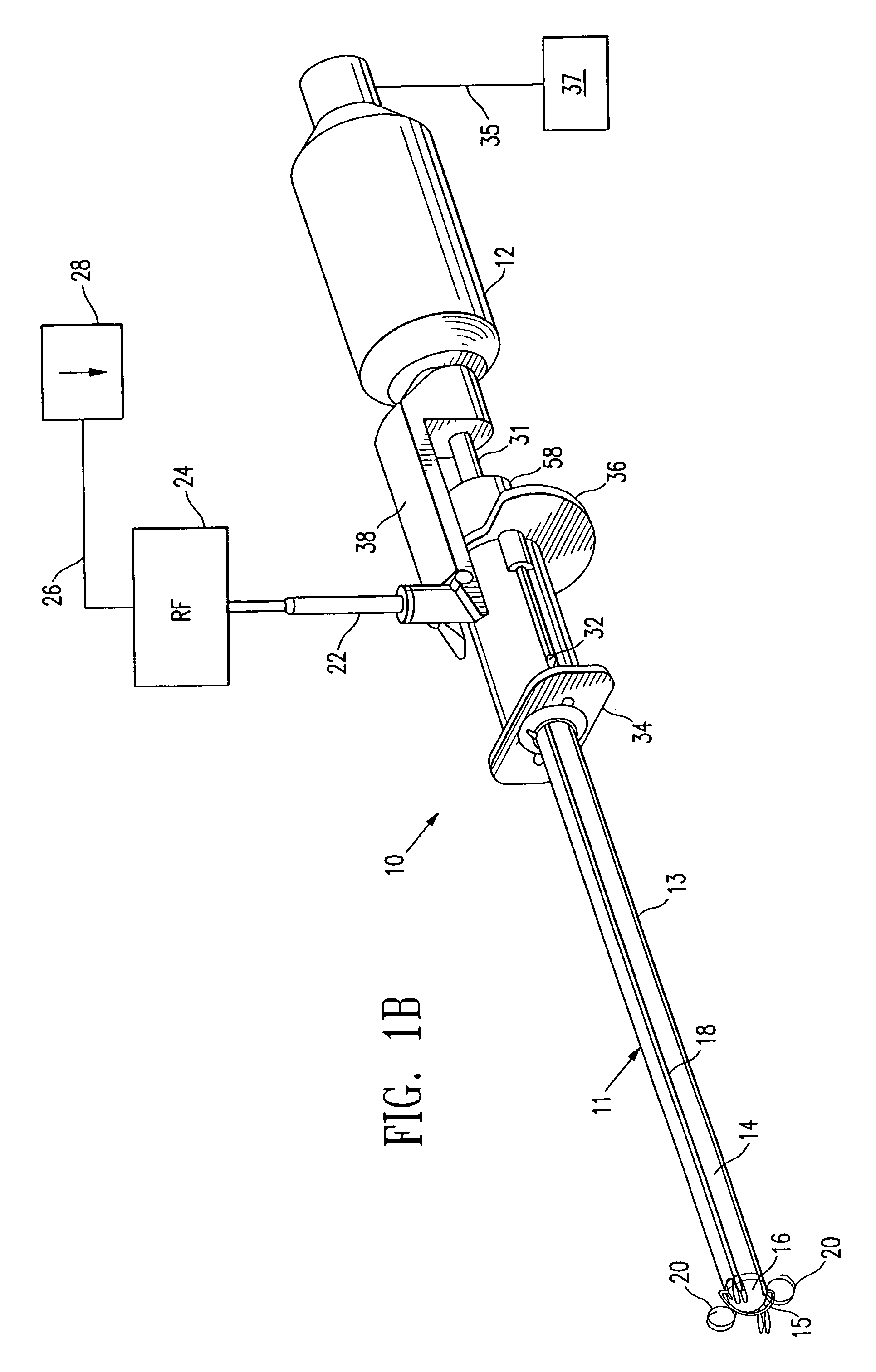
[0059]FIGS. 1A and 1B show a system 10 embodying features of the invention, which includes a sentinel node accessing and anchoring device 11, and an elongated radiation detector 12. The accessing and anchoring device has a shaft 13 with a proximal portion and a distal portion 14 with a cutting wire 15 at its tip 16; and a source of radio frequency (RF) power 24 connected to the cutting wire 15 via RF connector 22. The shaft 13 and radiation detector 12 lie generally along longitudinal axis 30. As shown in FIGS. 1A and 1B, cutting wire 15 is a tissue cutting member that may be activated by RF energy and is configured to ablate and penetrate tissue. It is shown as an arcuate wire spaced distally from the tip 16 of shaft 13. In alternative embodiments, cutting wire 15 may take other shapes and may be in contact with or form part of tip 16.

[0060]Radiation energy detector 12 includes an elongated probe 31, shown in FIGS. 4 and 6, and may be, e.g., a gamma probe. Radiation energy detector...


PUM


Abstract

The invention provides systems, methods and a node accessing and anchoring device, comprising an elongated shaft, a tissue cutting member, at least one anchoring element extending from a position at or near the distal end of the shaft; and a radiation detector. The radiation detector is effective to locate and identify sentinel lymph nodes following injection of radioactive material into a primary lesion site within a patient. The tissue cutting member, which may be activated with radio frequency energy, is effective to allow access of the elongated shaft to a sentinel lymph node. The anchoring elements are effective to anchor the device to or adjacent a sentinel lymph node accessed by the device. Anchoring elements may assume radially, longitudinally, or mixed radially and longitudinally curved or coiled configurations when deployed.

Description

RELATED APPLICATIONS[0001]This application is a divisional of U.S. application Ser. No. 09 / 880,218, filed Jun. 12, 2001 now U.S. Pat. No. 6,679,851, which is a continuation-in-part of prior U.S. application Ser. No. 09 / 146,185, filed Sep. 1, 1998, now U.S. Pat. No. 6,540,693; U.S. application Ser. No. 09 / 159,467, filed Sep. 23, 1998, now U.S. Pat. No. 6,261,241; U.S. application Ser. No. 09 / 356,187, filed Jul. 16, 1999, now U.S. Pat. No. 6,312,429; U.S. application Ser. No. 09 / 477,255, filed Jan. 4, 2000, now U.S. Pat. No. 6,471,700; and U.S. application Ser. No. 09 / 727,112, filed Nov. 29, 2000 now U.S. Pat. No. 6,638,234. All of the above applications, and all patents and patent applications referred to below, are incorporated herein in their entirety.BACKGROUND OF THE INVENTION[0002]The invention relates to the field of medical devices and methods used in the treatment of diseases such as cancer which have the ability to metastasize within a patient's body. More specifically, the ...

Claims


Application Information

Patent Timeline
Patent Type & Authority Patents(United States)
IPC IPC(8): A61B10/00A61B10/02A61B17/00A61B17/34A61B18/00A61B18/14A61B19/00
CPCA61B17/00491A61B18/1477A61B18/148A61B18/1482A61B19/54A61B10/0266A61B10/02A61B6/4258A61B18/1487A61B18/1815A61B2010/0208A61B2017/00115A61B2017/00867A61B2017/3488A61B2018/00208A61B2018/00273A61B2018/00333A61B2018/00577A61B2018/00601A61B2018/00916A61B2018/00958A61B2018/1407A61B2018/1425A61B2018/1475A61B2019/5276A61B2019/5404A61B2019/5408A61B2019/542A61B90/39A61B2090/378A61B2090/3904A61B2090/3908A61B2090/392
Inventor BURBANK, FRED H.LUBOCK, PAULWARDLE, JOHNLOUW, FRANKQUICK, RICHARD L.
Owner SENORX
Why Eureka
Try Eureka