Quality control process for a structural bonded joint

a technology of structural bonded joints and quality control, which is applied in the field of manufacturing structures, can solve the problems of high cost of manufacturing and testing process of these test coupons, and achieve the effect of reducing the cost of the qualification process

Inactive Publication Date: 2009-03-03
AIRBUS OPERATIONS SL
View PDF6 Cites 3 Cited by
  • Summary
  • Abstract
  • Description
  • Claims
  • Application Information

AI Technical Summary

Benefits of technology

[0015]An advantage of the present invention with respect to the quality control processes using standard test coupons is that it allows replacing the manufacture and testing of said standard test coupons with the incorporation of small premanufactured devices representative of one of the sub-components of the joint which are bonded to the other sub-component in conditions similar to those of the real joint. The quality of the joint between sub-components is represented by the quality of the joint between the premanufactured device and the other sub-component, which is given by the stress necessary to cause the failure of the joint between both in a test which can be carried out in situ immediately after the manufacturing process, greatly simplifying and reducing the cost of the qualification process of said joints.
[0016]Other features and advantages of the present invention will be disclosed in the following detailed description of an illustrative embodiment of the object with respect to the attached drawings.DESCRIPTION OF THE FIGURES
[0017]FIG. 1 shows an elevational view with a partial section of a device 1 used in a quality control process according to the present invention, formed by a main body 11 which will be fixed to the surface of the element to be tested, and a disposable head 12 incorporating an indentation or housing for a tool—in the figure, a cylindrical housing 15 of hexagonal section for an Allen wrench—joined through a frangible neck 16. The main body 11 has a planar surface which will be the joining surface with the surface of the element to be tested, on which the joining adhesive 13, which may or may not be incorporated in the device itself, and a non-adherent release film 14—of polytetrafluoroethylene or the like—which may or may not be incorporated in the device itself, will be applied and will be partially interposed between the device 1 object of the invention and the surface of the element to be tested.
[0018]FIG. 2 shows an isometric projection view of the device 1 installed on the surface of the element 17 to be tested.
[0019]FIG. 3 shows the same view as FIG. 2 and depicts the rod of the tool 18 introduced in its housing 15 and by means of which two cases of different loads can be applied on the device, each stress represented by means of an arrow: a torque 19 on the axis of symmetry of the device and a stress 20 with its corresponding resulting bending moment in the notch of the frangible neck 16.
[0020]FIG. 4 shows the same view as FIG. 3 and schematically shows the application of a torque 19 on the axis of symmetry of the device 1 causing the fracture of the frangible neck 16 and the detachment of the disposable head 12, characteristic of a correct adhesive joint.

Problems solved by technology

These adhesive joints, having numerous advantages compared to traditional riveted joints (they save in assembly operations, they are lighter, more rigid and have lower stress concentrations, they are leak-tight, etc), have an important drawback: both the materials used in said joint and the environmental conditions and handling conditions must be perfectly controlled at all times and the manufacture and testing of test coupons representative of said joint is necessary to assure the quality thereof.
The cost of the manufacturing and testing process of these test coupons is high, it further being difficult to assure that the configuration of the test coupons and manufacturing conditions are identical to those of the represented part, therefore the results obtained are only an approximation to the real conditions of the represented joint.

Method used


Image

  • Quality control process for a structural bonded joint
  • Quality control process for a structural bonded joint
  • Quality control process for a structural bonded joint

Examples


Embodiment Construction

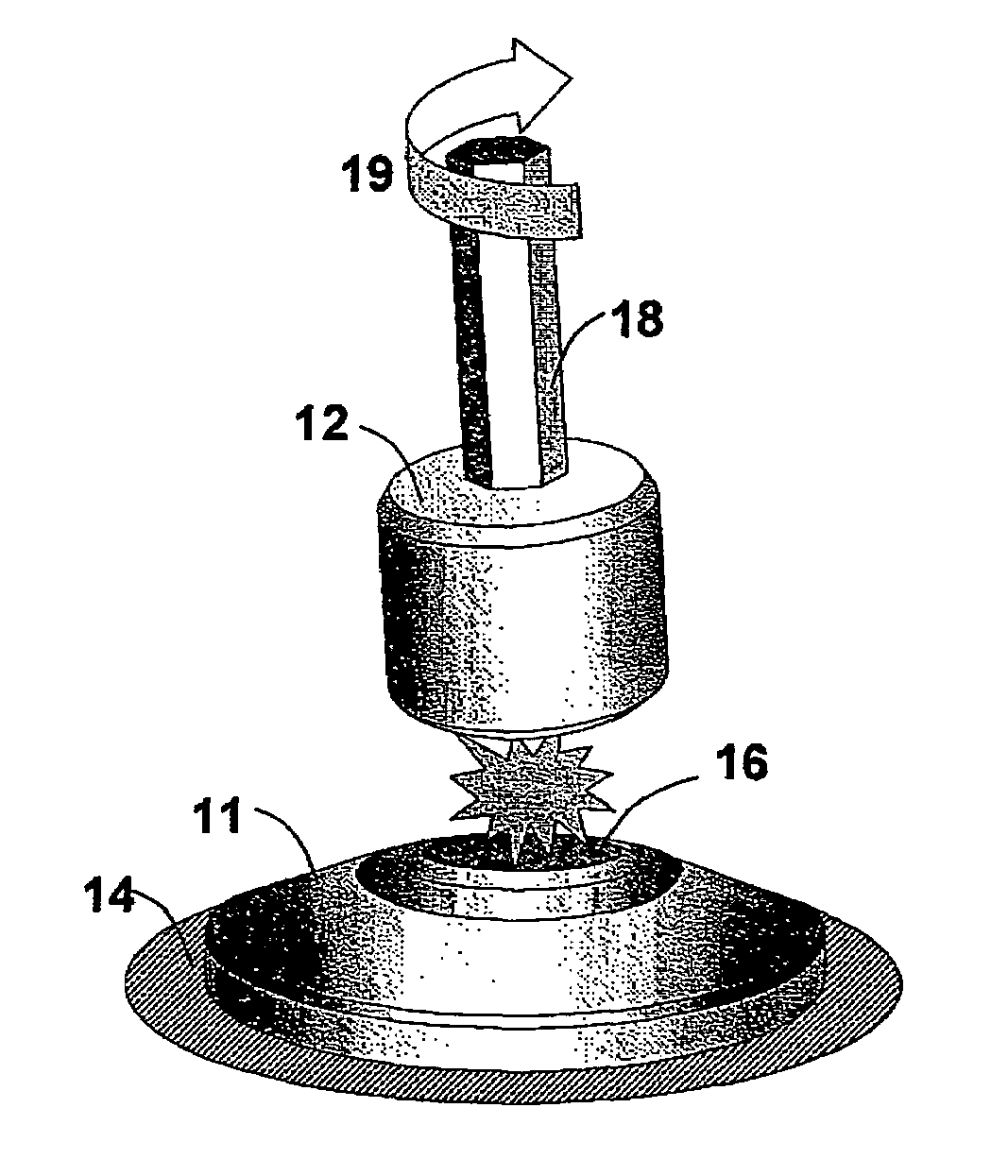
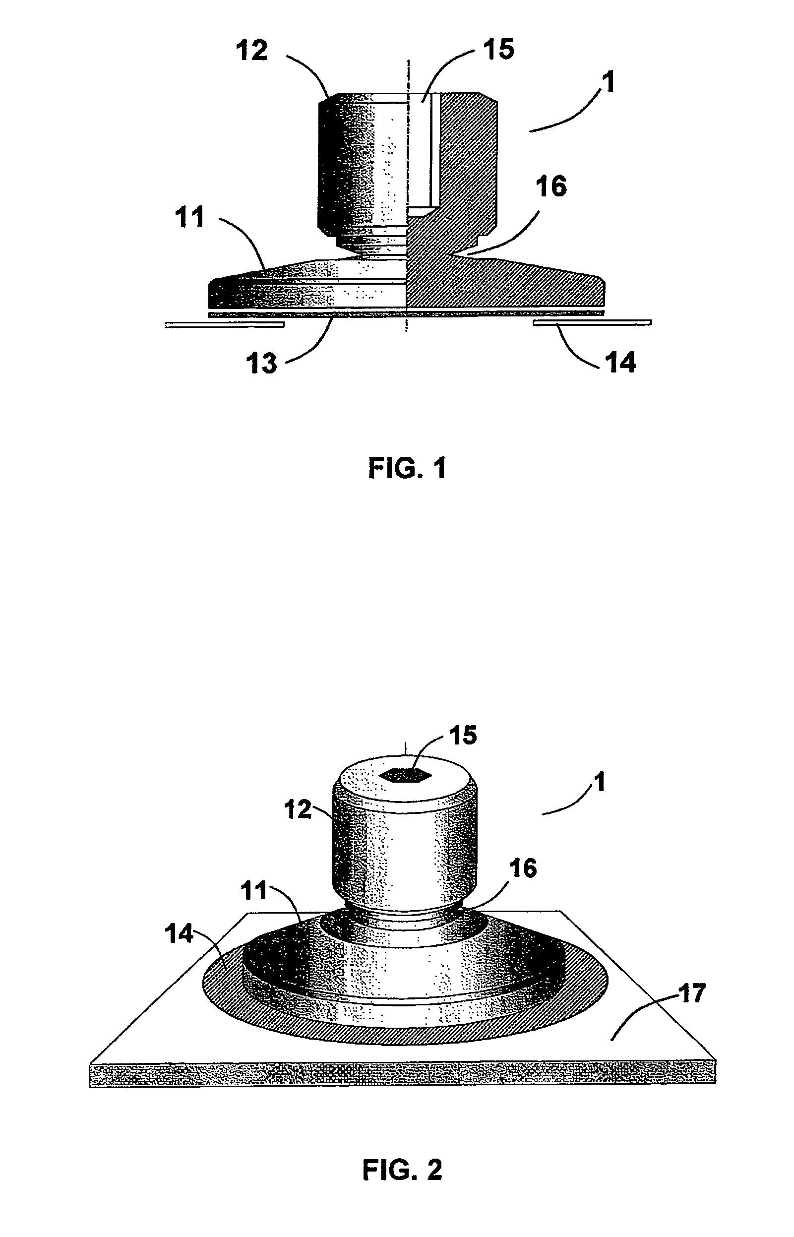
[0028]FIGS. 1 and 2 show a front view with a partial section and an isometric projection view of the premanufactured testing device 1 used in a preferred embodiment of the present invention object of the invention, the function of which is to replace the standard test coupons used to certify the quality of structural adhesive joints. The device 1 allows testing the quality of co-bonded joints (adhesive joints between precured elements of composite material and elements of composite material without curing) and secondary bonded joints (adhesive joints between precured elements of composite material or solid metallic and / or non-metallic elements generally).

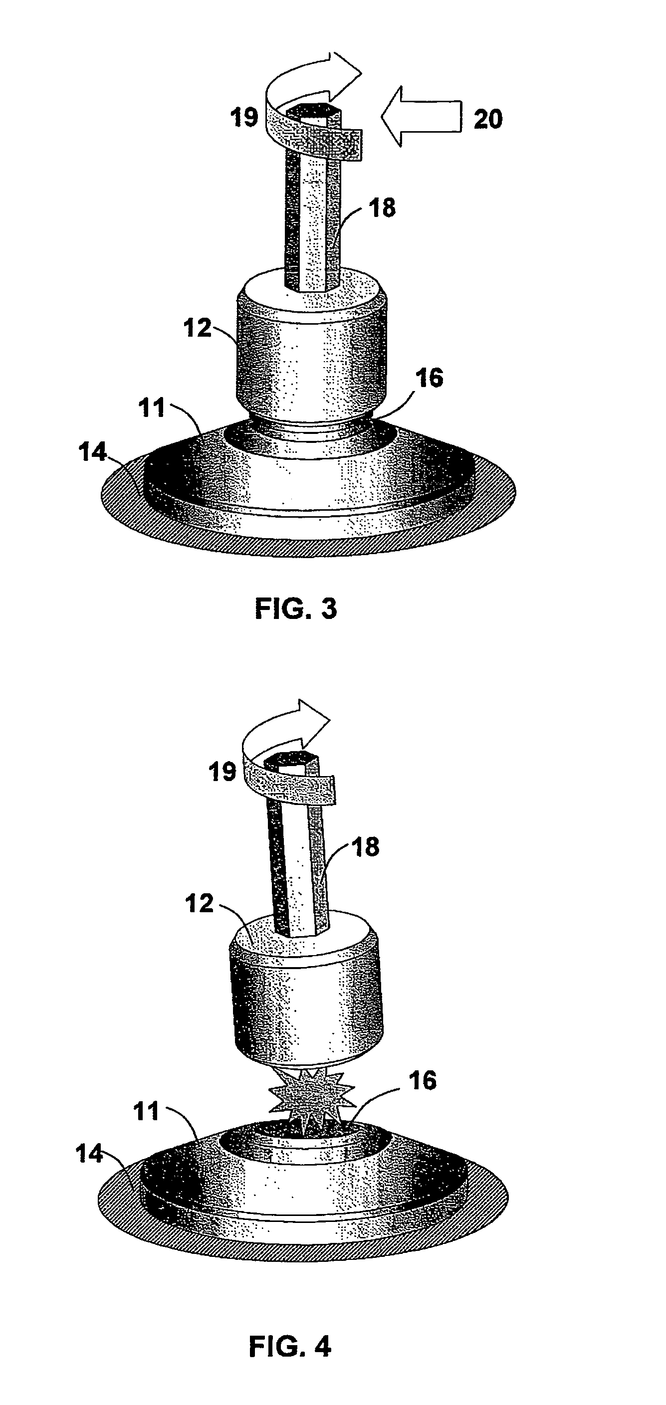
[0029]The device 1 is formed by a main body 11 which will be fixed to the surface of the element 17 to be tested and a disposable head 12 joined through a frangible neck 16. The head 12 incorporates an indentation or housing 15 for introducing a tool 18 in it, for example an Allen wrench.

[0030]The main body 11 of the device has a pl...


PUM

PropertyMeasurementUnit
adhesiveaaaaaaaaaa
mechanical testaaaaaaaaaa
shearing strength testaaaaaaaaaa

Abstract

The invention relates to a quality control process for an adhesive joint of two sub-components of a structure comprising the following steps: a) Providing the structure of composite material to be controlled; b) Providing at least one premanufactured testing device (1) representative of one of the sub-components of the structure; c) Bonding the at least one premanufactured testing device (1) to the other sub-component (7) of the structure in conditions similar to those of the real adhesive joint of the sub-components; d) Carrying out at least one mechanical test on the at least one premanufactured testing device (1) which allows assessing the quality of the adhesive joint.

Description

FIELD OF THE INVENTION[0001]The invention is included within the field of manufacture of structures incorporating joint consolidation processes of several sub-components (for example, co-curing of sub-components of structures of composite material formed by a discontinuous reinforcement of fibers or the like and a continuous matrix of thermoset resin or the like) and / or adhesive-joints of several sub-components (for example, bonding of sub-components of structures of composite or metallic materials), specifically in those technological areas requiring additional tests of standard test coupons representative of said joints certifying the quality thereof due to safety issues.BACKGROUND OF THE INVENTION[0002]The intensive introduction of advanced composite materials in primary structures has become a fundamental procedure for structural optimization (based on weight saving and the improvement of mechanical properties), one of the priority objectives in the design and manufacture of a n...

Claims


Application Information

Patent Timeline
Patent Type & Authority Patents(United States)
IPC IPC(8): G01N19/04G01N3/08
CPCG01N19/04
Inventor MENENDEZ MARTIN, JOSE MANUELSANCHEZ FERNANDEZ, JULIAN
Owner AIRBUS OPERATIONS SL
Why Eureka
Try Eureka