Optical branching-coupling device, and manufacturing method and optical module of the same

a branching coupling and optical technology, applied in the direction of instruments, applications, other domestic objects, etc., can solve the problems of increasing the production cost of the optical branching coupling device, the detachment of the half mirror, and the inability to optimally conduct the branching part of the optical branching coupling or optical branching coupling, so as to reduce the size of the space, reduce the cost of components and the number of steps, and simplify the effect of the number of steps

Inactive Publication Date: 2009-12-31
TOYODA GOSEI CO LTD
View PDF10 Cites 4 Cited by
  • Summary
  • Abstract
  • Description
  • Claims
  • Application Information

AI Technical Summary

Benefits of technology

[0017]According to the present invention, since the optical branching-coupling device can be manufactured without using half mirrors and the like which are costly, the component cost and the number of steps can be reduced and simplified, and the entire production cost can therefore be controlled. In addition, not using half mirrors and the

Problems solved by technology

When the branched core is formed of the above-mentioned self-written optical waveguide in which a half mirror is utilized, optical branching or optical coupling is not always ideally conducted in the branching part.
Thus, the half mirror is expensive, causing the production cost of the optical branching-coupling device to be increased.
For example, adding a thermal history to the optical branching-co

Method used


Image

  • Optical branching-coupling device, and manufacturing method and optical module of the same
  • Optical branching-coupling device, and manufacturing method and optical module of the same
  • Optical branching-coupling device, and manufacturing method and optical module of the same

Examples


example 1

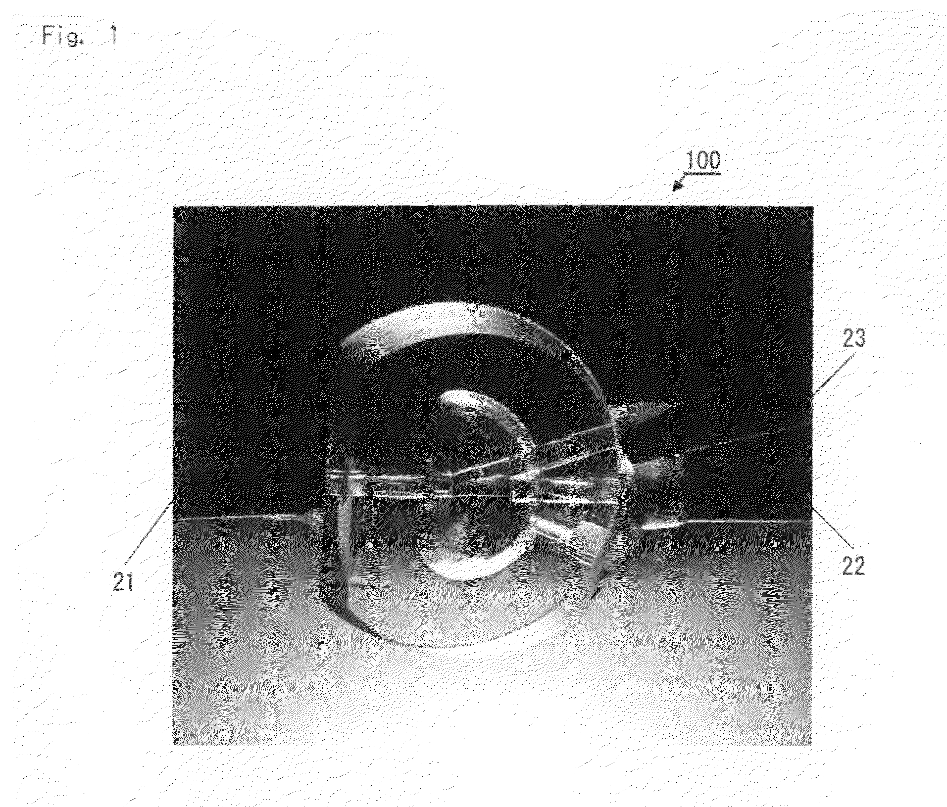
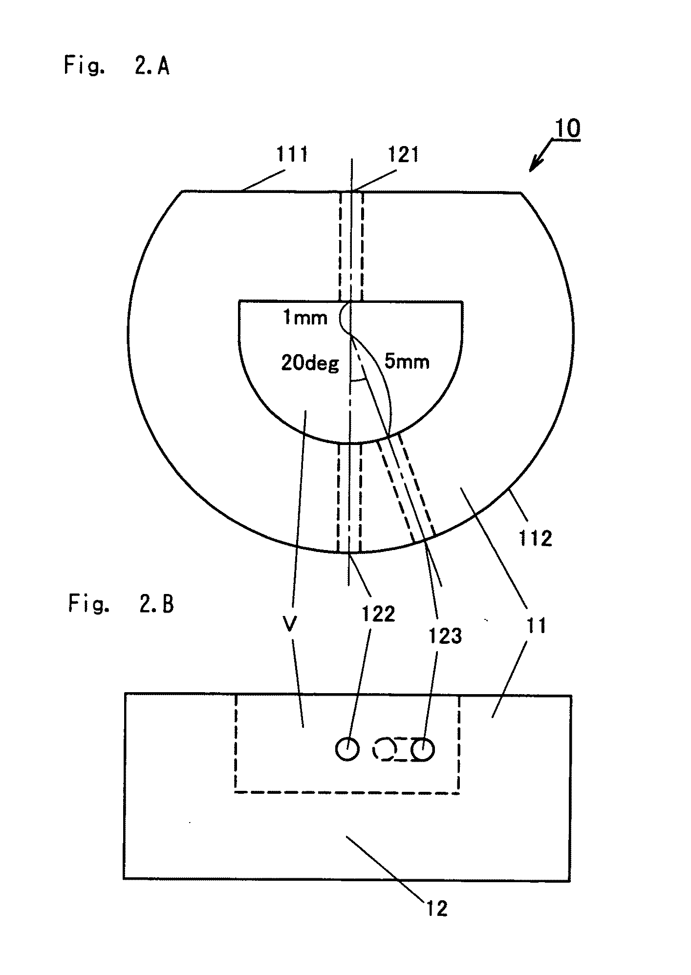
[0036]An optical branching-coupling device 100 according to the present invention was manufactured. FIG. 1 is a photograph thereof. The optical branching-coupling device 100 is an optical branching-coupling device having three plastic optical fibers (POFs) 21, 22, and 23. A housing 10 of the optical branching-coupling device 100 was manufactured in accordance with the design drawings of FIGS. 2A and 2B. FIGS. 2A and 2B are a plan view and a front view of the housing 10, respectively.

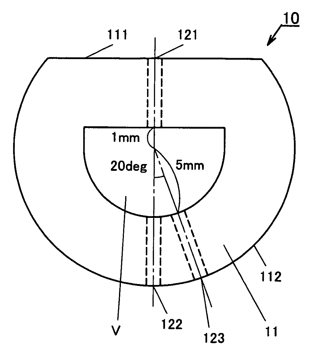
[0037]As FIGS. 2A and 2B show, the housing 10 has a D-shaped sidewall 11 and a bottom part 12, and an approximately semi-columnar region V having an open top part and being surrounded by the D-shaped side wall 11 and the bottom part 12. The housing 10 also has three optical fiber insertion holes 121, 122, and 123 in the D-shaped side wall 11 which are penetrating hole parts having a columnar side face. The optical fiber insertion hole 121, which is a penetrating hole part having a columnar side face, is ...

example 2

[0043]FIG. 5 is a plan view illustrating the structure of an optical module 200 according to the present invention. The optical module 200 of FIG. 5 has a transparent housing 10′, and a first optical waveguide core 31 and a second optical waveguide core 32 which form the branch part 33 without using half mirrors in the transparent housing. Both the cores of the first optical waveguides 31 and the second optical waveguide 32 consist of a cured material of a light-curing resin, which is manufactured by a manufacturing technique of a self-written optical waveguide. The optical module 200 further includes a receptacle 102 optically connected with a first optical input-output port 311 which is the end face of the first optical waveguide core 31; a PD 40 optically connected with a second optical input-output port 312 which is the end face of the first optical waveguide core 31 through the transparent housing 10′; and an LED 50 optically connected with a third optical input-output port 323...


PUM


Abstract

The optical branching-coupling device having a self-written optical waveguide core is formed without using half mirrors. In the optical branching-coupling device, three POFs are inserted into a housing having an approximately D-shaped sidewall. An approximately semi-columnar region V in the housing was filled with an uncured liquid light-curing acrylic resin. A laser beam was introduced from one of the POFs, and a cured material was formed of the end face of the POF. The diameter was equal to the core diameter of the POF. The cured material grew, resulting in the cured material reaching the end face of another one of the POFs, thereby forming an optical waveguide core. Next, a laser beam was introduced from the end face of the last one of the POFs. The cured material grew, resulting in a connection with the optical waveguide core, thereby forming the optical waveguide core.

Description

BACKGROUND OF THE INVENTION[0001]1. Field of the Invention[0002]The present invention relates to an optical branching-coupling device usable as an optical branching device and an optical coupling device, and an optical module containing the same, and a manufacturing method of an optical branching-coupling device.[0003]2. Description of the Related Art[0004]In optical communication, optical branching-coupling devices and optical modules containing an optical branching-coupling device and a light emitting device and a light receiving device have a crucial role. For example, in single wire bidirectional optical communication, an optical branching and coupling device which branches and couples an optical waveguide for propagating the light emitted from a light emitting device such as an LED, an LD, or the like and an optical waveguide for propagating the transmitted light to a light receiving device such as PD is required at input-output terminal of the system. Meanwhile, the applicants...

Claims


Application Information

Patent Timeline
IPC IPC(8): G02B6/26
CPCG02B6/125G02B6/30G02B6/138
Inventor HAGA, KENJIINUI, YUKITOSHITERADA, KAZUHIROOKITA, AKIKOTSUCHIMORI, MASAAKINAKAO, AKARI
Owner TOYODA GOSEI CO LTD
Why Eureka
Try Eureka