Adhesive tape printer

a tape printer and adhesive technology, applied in printing, typewriters, coatings, etc., can solve the problem of large and achieve the effect of reducing the space required for providing the apparatus and improving user convenien

Active Publication Date: 2013-11-07
BROTHER KOGYO KK
View PDF3 Cites 6 Cited by
  • Summary
  • Abstract
  • Description
  • Claims
  • Application Information

AI Technical Summary

Benefits of technology

[0007]It is therefore an object of the present disclosure to provide an adhesive tape printer capable of decreasing the size of the space for providing the apparatus.
[0011]With the configuration of each of the components such as described above, according to the adhesive tape printer of the present disclosure, the housing which contains each of the components can be designed with a narrow width shape, comprising a long dimension in the direction along the one side and the other side of the first horizontal direction (front-rear direction, for example), and a short dimension in a second horizontal dimension orthogonal to the one side and the other side in the first horizontal direction (left-right direction, for example). As a result, it is possible to decrease the space required for providing the apparatus.
[0012]Further, the first opening / closing cover capable of opening and closing the first storage part, and the second opening / closing cover capable of opening and closing the second storage part are provided to the upper part of the housing. Then, it is possible to expose the first storage part by opening the first opening / closing cover provided to the one side end (rear end, for example) in the first horizontal direction, and expose the second storage part by opening the second opening / closing cover provided to the other side end (front end, for example) in the first horizontal direction. That is, it is possible to individually and independently expose the first storage part and the second storage part, respectively. With this arrangement, in the use mode where the adhesive tape with print is wound inside the second storage part, forming the second roll, for example, it is also possible to open the second opening / closing cover based on suitable timing and remove and use the second roll wound inside the second storage part, regardless of the consumed state of the print-receiving adhesive tape of the first roll inside the first storage part. Thus, it is possible to improve user convenience.

Problems solved by technology

Nevertheless, the prior art has the following problems.
As a result, the problem arises that a large space is required for providing the apparatus.

Method used


Image

  • Adhesive tape printer
  • Adhesive tape printer
  • Adhesive tape printer

Examples


Embodiment Construction

[0044]The following describes one embodiment of the present disclosure with reference to accompanying drawings. Note that, in a case where “Front,”“Rear,”“Left”, “Right,”“Up,” and “Down” are denoted in the drawings below, the terms front, rear, left, right, up, and down in the explanations within the description refer to the denoted directions. Furthermore, in this definition, the front-rear direction corresponds to the first horizontal direction in the claims, the rear side corresponds to the one side in the first horizontal direction (or simply the “one side in the horizontal direction”), and the front side corresponds to the other side in the first horizontal direction (or simply the “other side in the horizontal direction”). Further, the left-right direction corresponds to the second horizontal direction.

General Configuration of Adhesive Tape Printer

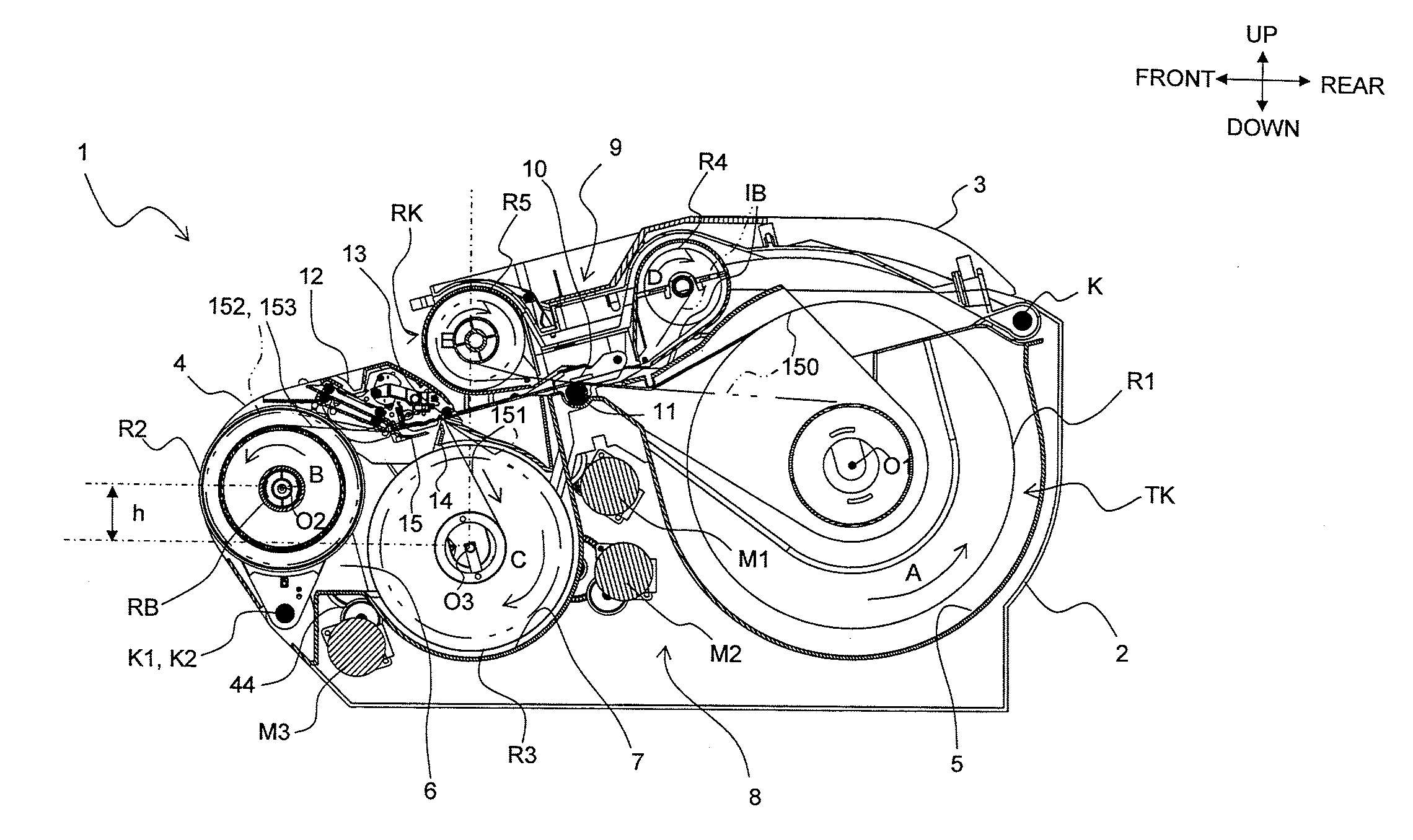
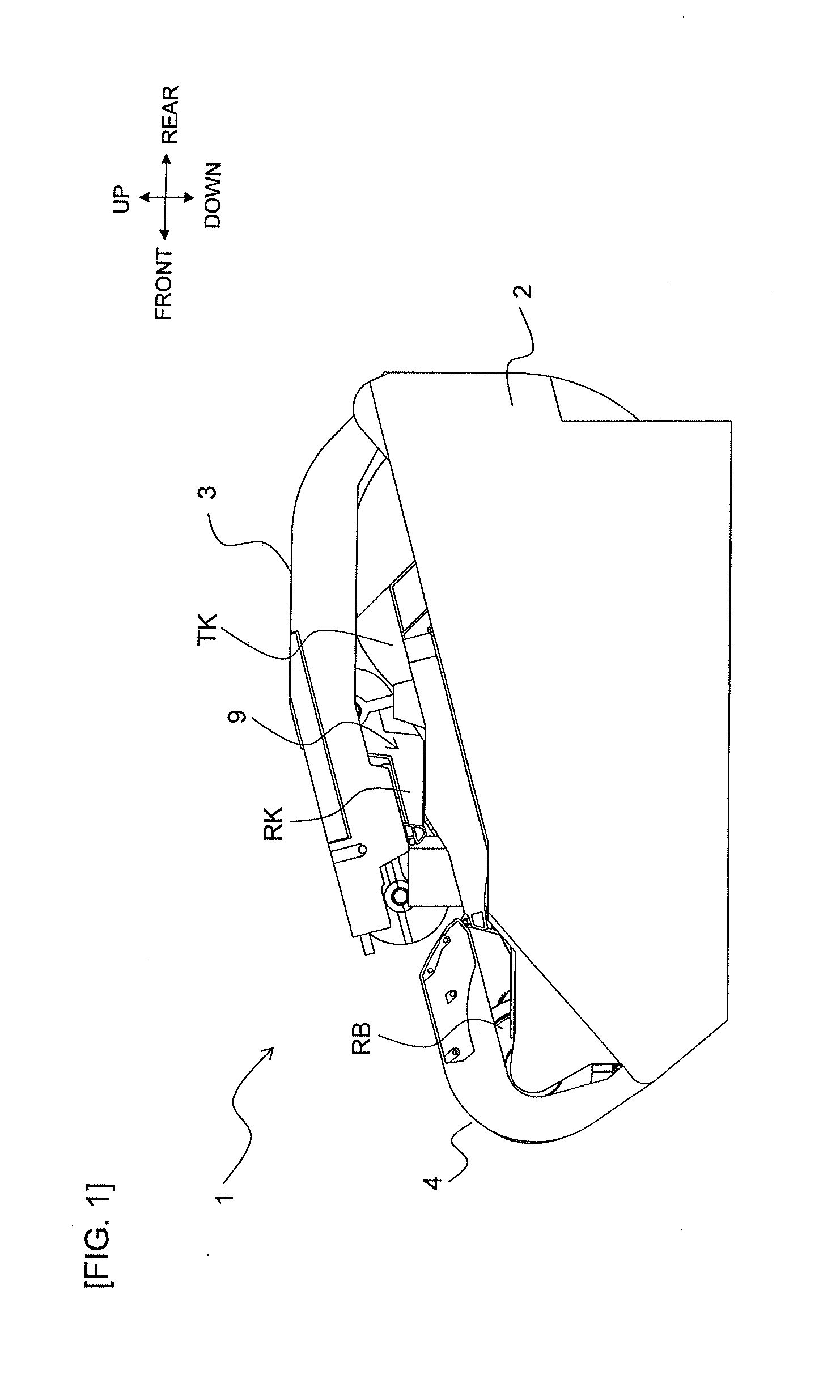
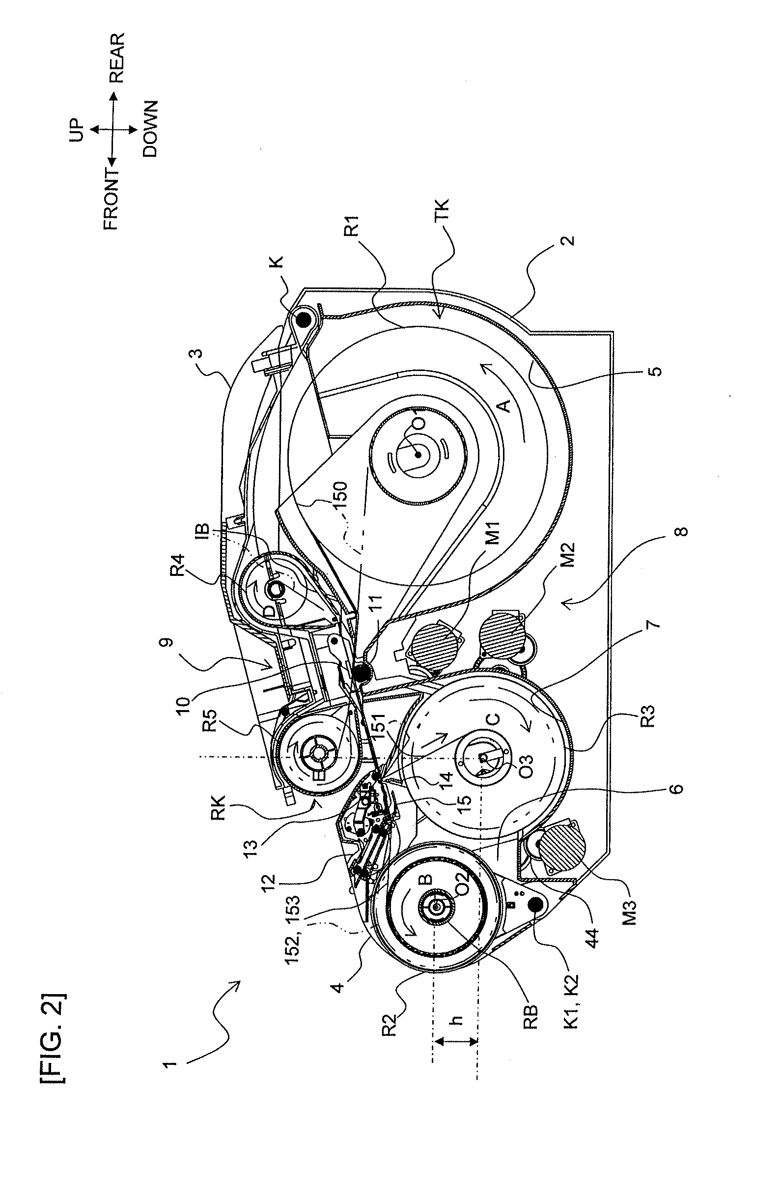
[0045]First, the general configuration of the adhesive tape printer will be described based on FIGS. 1-6.

[0046]In FIGS. 1-6, an adh...


PUM


Abstract

This disclosure discloses an adhesive tape printer comprising a housing, a first storage part configured to receive a first roll provided to one side of the housing in the first horizontal direction, a feeding roller, a printing head, a second storage part configured to store a second roll wherein the adhesive tape with print is wound around an axis line in the second horizontal direction, provided to the other side of the housing in the first horizontal direction, a feeding motor provided further on the other side than the first storage part and further on the one side than the second storage part so that an axis direction of an output shaft matches the second horizontal direction, a first opening / closing cover provided to an upper part on the one side, and a second opening / closing cover provided to an upper part on the other side.

Description

CROSS-REFERENCE TO RELATED APPLICATION[0001]The present application claims priority from Japanese Patent Application No. 2012-105357, which was filed on May 2, 2012, the disclosure of which is incorporated herein by reference in its entirety.BACKGROUND[0002]1. Field[0003]The present disclosure relates to an adhesive tape printer that performs desired printing on an adhesive tape (print-receiving adhesive tape) that serves as a print target.[0004]2. Description of the Related Art[0005]Adhesive tape printers configured to form desired print on a print-receiving adhesive tape and form an adhesive tape with print are already known. According to this prior art, an openable and closeable cover is provided to an upper part of an apparatus main body (label printer main body) of a flat, horizontal box shape. During apparatus operation, with the cover set to a closed state, a print-receiving adhesive tape roll, wherein a print-receiving adhesive tape is wound around an axis line, is mounted t...

Claims


Application Information

Patent Timeline
Patent Type & Authority Applications(United States)
IPC IPC(8): B41F17/10B41F19/00
CPCB41F17/10B41F19/00B41J3/4075B41J15/044
Inventor TANAKA, MITSUGI
Owner BROTHER KOGYO KK
Why Eureka
Try Eureka